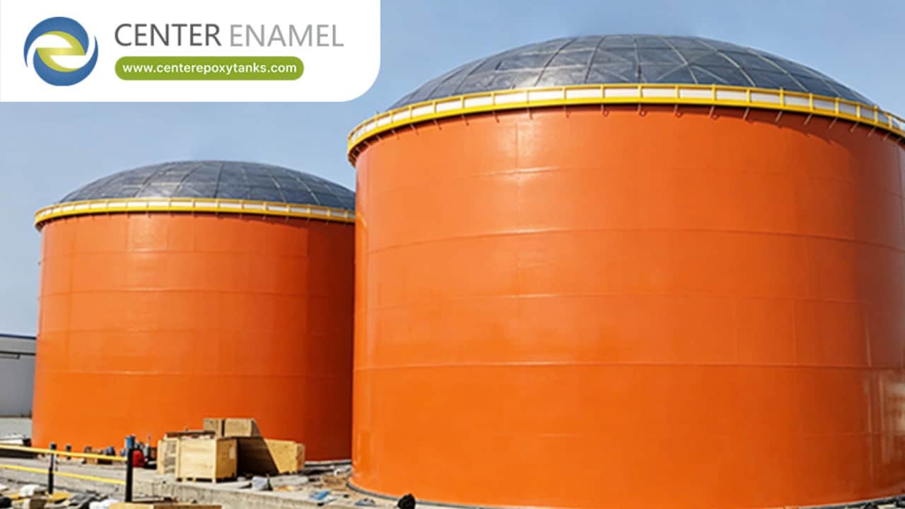
Welded Steel Tank Design & Engineering: Standards, Calculations, and Best Practices
In industrial bulk liquid containment—spanning petroleum refineries, chemical processing plants, and municipal water reserves—structural safety and regulatory compliance begin on the drawing board. Welded steel tank design and engineering requires a precise balance of mechanical metallurgy, structural physics, and strict adherence to international codes.
Because field-erected storage vessels hold millions of gallons of volatile hydrocarbons or vital water supplies under intense hydrostatic load, engineers must master foundational calculation methodologies and material standards to ensure a 50-year operational lifespan.
1. Governing Engineering Codes and Standards
Before structural calculations commence, the lead engineer must establish the governing standard based on the stored media, operational pressure, and local jurisdiction:
API 650 (Welded Tanks for Oil Storage): Published by the American Petroleum Institute, API 650 is the global benchmark for atmospheric and low-pressure (up to 2.5 psig) vertical cylindrical tanks storing petroleum products, chemicals, and industrial liquids.
AWWA D100 (Welded Carbon Steel Tanks for Water Storage): Published by the American Water Works Association, AWWA D100 governs welded steel tanks dedicated to municipal water supplies, ground reservoirs, standpipes, and fire protection systems.
ASME Section VIII / Section IX: Provides supplementary rules for pressure vessel compliance, material specifications, and certified welding procedures (WPS/WPQ).
2. Core Structural Calculation Methodologies
Designing a safe field-erected welded tank involves evaluating multiple interactive load paths and stress limits:
A. One-Foot Method and Variable-Design-Point Method for Shell Thickness
To withstand the crushing hydrostatic head pressure exerted by stored liquids, tank shells are engineered with decreasing plate thickness from bottom to top.
Hydrostatic Pressure Formula: Shell thickness calculations account for liquid density, tank radius, height, and allowable material stress. Lower shell courses receive heavy carbon steel plates (e.g., ASTM A516 Grade 70), while upper courses transition to thinner structural grades (e.g., ASTM A36).
B. Wind Shear and Seismic Overturning Stability
Wind Loading: Evaluated via ASCE 7 or API 650 Appendix F, accounting for regional wind speeds, exposure categories, and aerodynamic stability on open-top or fixed-roof structures.
Seismic Analysis: API 650 Appendix E and AWWA D100 / ASCE 7 mandate rigorous hydrodynamic sloshing analyses. Engineers calculate convective and impulsive liquid forces to determine whether mechanical anchor bolts or self-anchored ringwall foundations are required to prevent seismic overturning.
Data Table: Engineering Comparison of API 650 vs. AWWA D100 Design Parameters
Engineering Parameter | API 650 (Petroleum & Industrial) | AWWA D100 (Municipal Water Storage) |
Primary Target Media | Crude oil, refined fuels, chemicals, industrial water | Potable water, raw water, municipal fire protection |
Maximum Design Pressure | Atmospheric up to 2.5 psig internal pressure | Atmospheric storage water systems |
Minimum Shell Plate Thickness | Governed by diameter and structural class rules | Strict minimum plate rules (typically 1/4 inch or greater for wetted parts) |
Seismic Calculation Basis | Appendix E (Self-contained flat-bottom rules) | ASCE 7 referencing hydrodynamic sloshing and ringwall design |
Weld Examination Standards | Radiographic (RT) or Ultrasonic (UT) shell testing | Mandatory UT/RT schedules for butt welds and structural risers |
3. Detailing Nozzles, Shell Manways, and Appurtenances
Engineering a welded tank extends beyond the primary shell to include precise detailing for operational access and piping connections:
Reinforcement Calculations (Repads): Whenever openings are cut into the tank shell for access manways or fluid nozzles, structural continuity is disrupted. Engineers calculate reinforcement pad (repad) dimensions using API 650 Appendix J or AWWA D100 formulas to compensate for stress concentrations around cutouts.
Corrosion Allowance: Designing an extra margin of metal thickness (typically 1/16 to 1/8 inch) into shell and floor plates guarantees structural integrity even if minor interior oxidation occurs over decades of service.
Frequently Asked Questions (FAQ)
Q: What are the primary engineering standards for welded steel tank design?
A: The two primary global benchmarks are API 650 for petroleum, chemical, and industrial storage, and AWWA D100 for municipal water storage systems.
Q: How is tank shell plate thickness determined during engineering design?
A: Shell thickness is calculated using hydrostatic head pressure formulas (such as the one-foot method or variable-design-point method), ensuring plates are thicker at the bottom where liquid pressure is highest and thinner toward the top.
Q: Why are reinforcement pads (repads) required around tank manways and nozzles?
A: Cutting openings into a tank shell weakens the local structural matrix. Engineers design repads around manways and nozzles to redistribute hoop stresses and maintain structural compliance under full load.
Q: How does seismic design impact welded steel tank engineering?
A: In high-seismic zones, engineers perform complex hydrodynamic and sloshing analyses per ASCE 7 or API 650 Appendix E, which frequently dictates shell thickness adjustments and requires engineered foundation anchor bolts to prevent tank overturning.