Selecting a Chilled Water Buffer Tank for Data Center Cooling Loops
Selecting a chilled water buffer tank for a data center cooling loop is a balance of hydraulic need, footprint, and material compatibility. Oversize and you waste space; undersize and the chillers still short-cycle. This article gives the selection criteria that matter.
Select a chilled water buffer tank from the flow differential between chiller and load sides and the allowable temperature swing, then choose geometry and material for the site. For data-center loops, volume is typically sized so the chiller sees stable minimum flow; GFS or stainless bolted shells suit atmospheric duty, while ASME vessels cover pressurized buffer duties. Prioritize clean primary-secondary connections and corrosion-compatible liners.
Sizing the Buffer Volume
The buffer must absorb the instantaneous flow mismatch between primary and secondary loops. Sizing uses the design flow differential and the permitted temperature change across the tank over the control interval.
A common rule is to provide enough volume that the chiller minimum flow is maintained through the worst-case load swing.
Geometry and Material Selection
Aspect ratio follows site footprint and available height. Material follows water chemistry: GFS for broad resistance, stainless for aggressive or high-purity loops, FBE for economy. Pressurized buffer vessels are ASME-coded steel.
Because the buffer sees continuous flow, corrosion protection and internal finish quality directly affect lifetime and water quality.
Connections and Commissioning
Specify nozzle positions for primary and secondary connections, drains, and sensors. Clean, low-turbulence entry preserves any incidental stratification and simplifies balancing during commissioning.
Technical Specifications
Parameter | Specification |
Sizing basis | Flow differential x time |
Goal | Stable chiller min flow |
Aspect ratio | Site-driven |
Atmospheric material | GFS / stainless / FBE |
Pressurized | ASME Section VIII |
Connections | Primary + secondary |
Sensors | Temp + flow |
Shell | Atmospheric / low-pressure |
Standard | AWWA D103 / ASME |
QA | ISO 9001 |
Verified Tank Engineering Reference
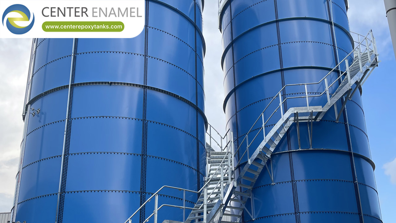
Center Enamel's multi-tank bolted projects - such as a 2025 Malaysian installation of four GFS tanks at 17.58 m diameter and 20,380 m3 - show the capability to deliver several coordinated shells (buffer, TES, or fire) on one campus. Capability evidence only.
Project location | Malaysia |
Application | Drinking water |
Tank type | GFS (Glass-Fused-to-Steel) bolted tank |
Scale | 4 unit(s), φ17.58*21m(H) |
Total volume | 20,380 m3 |
Year | 2025-10 |
Note | Cited as manufacturing-capability evidence, not a data-center project. |
Center Enamel Capability
Center Enamel offers atmospheric bolted buffer tanks and ASME pressure vessels from one quality system (ISO 9001), simplifying procurement for campuses needing both. Bolted tanks are built to AWWA D103 and ISO 28765 with available NSF/ANSI 61 and WRAS certification.
The engineering team supports nozzle and connection layout so the buffer integrates cleanly with the primary-secondary break.
Frequently Asked Questions
Q: How is a buffer tank sized?
A: From the flow differential between chiller and load sides and the allowed temperature swing over the control interval.
Q: What material should I choose?
A: GFS for broad corrosion resistance, stainless for aggressive loops, FBE for economy; pressurized buffers are ASME steel.
Q: Can the buffer also store energy?
A: It can provide minor buffering, but true energy time-shift needs a dedicated TES tank sized for hours, not minutes.
Q: Where are the connections?
A: Primary and secondary nozzles at the decoupling point, plus drains and sensor ports.
Q: Does the buffer need ASME coding?
A: Only if it is pressurized; atmospheric buffers follow AWWA D103.
Q: Why does material matter for a buffer?
A: Continuous flow and water quality make corrosion protection and internal finish decisive for lifetime.
Selecting a chilled water buffer tank is about hydraulic fit first: size for flow differential, choose geometry for the site, and pick a corrosion-compatible liner. Get those right and the chillers run steady.
Suggested Next Step
Share your loop flow rates and water analysis - we will size and specify a buffer tank with connection details for your plant.