Target Metadata
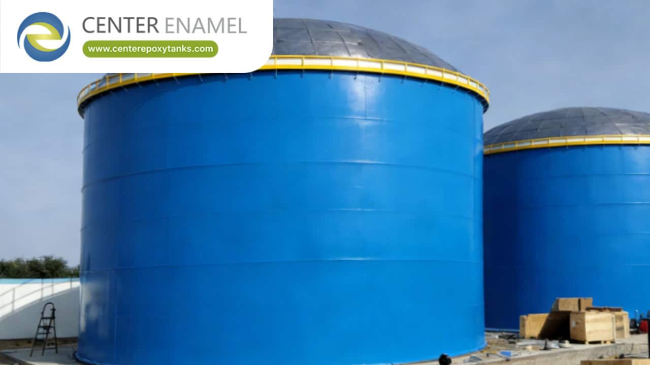
Hydraulic Oil Tanks: Reservoir Design for Power and Lubrication Systems
The hydraulic reservoir is the most underrated component in any power unit: too small and the oil runs hot and foamy, too dirty and valves score, too poorly baffled and air bubbles ride straight back into the pump. Good reservoir design is what separates a hydraulic system that runs decades from one that eats pumps annually.
Hydraulic oil tanks are reservoirs in hydraulic power units that store, deaerate, settle, and cool the working fluid, commonly sized at two to four times pump flow per minute, with internal baffles, air and water separation zones, and filtration access engineered to hold system cleanliness within target ISO 4406 codes.
1. How Should a Hydraulic Reservoir Be Sized?
Sizing balances heat dissipation against volume and duty cycle.
· The 3x rule: Classic sizing is 3 times maximum pump flow per minute — enough for dissolved air to escape and contamination to settle between passes.
· Duty cycle adjustment: Systems with long idle periods or high heat loads upsize; mobile machinery with compact HPUs trades volume for coolers.
· Thermal check: Reservoir surface area must dissipate the system's steady-state heat load, or the volume decision gets overridden by a cooler requirement.
· Freeboard and air space: Headspace accommodates thermal expansion and cylinder volume exchange without overflowing or sucking air.
2. What Internal Design Features Make a Reservoir Work?
Fluid conditioning happens inside the tank, not just storage.
· Baffle plates: A baffle extending about 60% of tank length separates return from suction zones, forcing a long settling path instead of a short circuit.
· Return-line placement: Returns discharge below the surface through diffusers — eliminating the waterfall aeration that damages pumps.
· Suction positioning: The pump suction sits away from the return zone and above the bottom so settled sludge is never ingested.
· Drain, cleanout, and slope: A sloped bottom with low-point drain and accessible cleanout covers makes the periodic cleaning real instead of theoretical.
3. How Is Contamination Controlled?
Most hydraulic failures are particle and water failures — the tank is the control point.
· Cleanliness targets: System sensitivity sets the ISO 4406 target — e.g., 18/16/13 for proportional valves and tighter for servo systems; reservoir fabrication and flushing must reach the target before commissioning.
· Breathing management: Every level cycle breathes air; desiccant breathers block moisture and particles, and sealed tanks with bladders eliminate breathing entirely.
· Water removal: Drain zones at the low point collect free water from condensation; oil samples verify water content within specification.
· Access for filtration: Off-line filtration loops and accessible magnet arrays turn the reservoir into an active cleaning station between services.
Data Table: Reservoir Sizing by Application
Application | Volume (x pump flow) | Key Feature |
Industrial HPU | 2.5-4x | Full baffling, offline filter |
Mobile machinery | 0.5-1.5x | Cooler, pressurized tank |
Lubrication skid | 1-2x | Settling zone, water drain |
Test stand | 3-5x | Heat exchanger, deaeration |
Servo system | 3x + sealed | Bladder or nitrogen blanket |
Frequently Asked Questions (FAQ)
Q1: How big should a hydraulic oil tank be?
The classical rule is three times maximum pump flow per minute — a 200 L/min pump pairs with a ~600 L reservoir. The multiplier adjusts for duty: high-idle systems upsize for cooling, mobile units compress volume and add heat exchangers.
Q2: Why do hydraulic tanks have baffles?
Baffles separate the return zone from the suction zone, forcing fluid to travel a long, slow path where air rises out, water separates, and particles settle before the fluid returns to the pump. A tank without effective baffling just circulates foam and contamination straight back into the system.
Q3: How do you keep hydraulic oil clean in the reservoir?
Specify and verify an ISO 4406 cleanliness target matched to the most sensitive component, fabricate and flush the tank to that target, then protect it: desiccant breathers against moisture, submerged returns against aeration, low-point drains for water, and off-line filtration loops for continuous polishing.
Q4: What material is best for hydraulic oil tanks?
Carbon steel with proper internal cleaning and coating is standard for industrial HPUs; stainless steel (304/316L) is specified for wash-down environments, offshore duty, and systems where rust from internal condensation cannot be tolerated. Welded stainless covers with sealed access keep contamination out of high-cleanliness reservoirs.