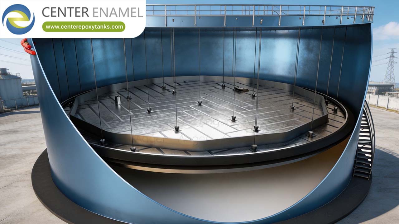
Floating Roof Hydraulic Oil Tanks - Keeping Air and Water Out of the Reservoir
Hydraulic oil fails for three reasons, in order: contamination, water, and air. Solids wear components, water degrades the oil and promotes corrosion, and entrained air causes spongy actuation, pump cavitation and rapid oil oxidation. A conventional vented reservoir exposes a large oil surface to the tank's own atmosphere, so every thermal cycle draws in moist air that condenses on the underside of the cover and drips back into the oil.
A floating roof or floating cover removes that surface. Engineered by Shijiazhuang Zhengzhong Technology Co., Ltd. (Center Enamel), a floating roof hydraulic oil tank covers the oil with a deck that rises and falls with level, so there is no wettable cover to condense on and no open surface to absorb air and moisture.
1. Why Use a Floating Cover on a Hydraulic Reservoir?
To remove the air-oil interface. With no open surface, moisture ingress and air entrainment both fall sharply, which directly extends oil life and reduces the load on filtration and vacuum dehydration.
· Air Exclusion: No open surface means far less air entrained during return flow and level changes.
· Moisture Control: With no cool cover above the oil, condensation cannot form and drip back.
· Oxidation Rate: Less dissolved oxygen means slower oil oxidation and longer oil life.
· Foam Behaviour: Reduced air entrainment reduces foam formation and the residence time it needs to break.
· Filtration Load: Less ingress means filters last longer and offline polishing is needed less often.
2. How Is Water Excluded and Removed?
By excluding it at the source with a sealed deck and a desiccant breather, and by removing what remains through a bottom drain, water-absorbing filtration or vacuum dehydration. The reservoir design supports all three.
· Sealed Deck: A floating cover with a rim seal removes the surface that would otherwise exchange moisture with the tank atmosphere.
· Desiccant Breather: Any remaining breathing path is fitted with a desiccant breather so incoming air is dried.
· Bottom Drain: The floor is arranged so free water collects at a drain point and can be removed routinely.
· Water Removal Plant: Filtration or vacuum dehydration is specified where the duty requires continuous water removal.
· Monitoring: Oil condition monitoring confirms the strategy is working rather than assuming it.
3. What Materials and Finishes Are Used?
Stainless steel where oil cleanliness is critical, coated carbon steel where it is not, with welded construction, smooth internal welds and a floor arranged for drainage and cleaning.
· Stainless Construction: 304L or 316L where product cleanliness and corrosion resistance justify the cost.
· Coated Carbon Steel: Used where the oil specification and the duty permit, with a coating compatible with hydraulic oil.
· Weld Quality: Internal welds are smooth and free of crevices so they can be cleaned and do not trap debris.
· Floor Design: Sloped or sumped so water and solids collect where they can be drained.
· Access for Cleaning: Manways and openings are positioned so the interior can be cleaned and inspected.
Evaluation Criterion | Floating Roof Reservoir | Vented Fixed Roof Reservoir |
Air-oil interface | Covered by deck | Full surface exposed |
Condensation on cover | None - no wettable cover above oil | Forms and drips back |
Moisture ingress | Very low | Continuous with breathing |
Foam and aeration | Reduced | Higher |
Oil life | Longer | Shorter |
Engineering Assurance and Project Support
Every welded oil tank delivered by Shijiazhuang Zhengzhong Technology Co., Ltd. (Center Enamel) is designed to API 650 with shell courses sized by the one-foot method and checked for wind, seismic and hydrostatic load cases, or to EN 14015 and the Eurocodes where the site is European. Shell plate is shot-blasted to Sa 2.5 and coated to a documented dry film thickness, longitudinal and annular plate welds are examined by radiography or ultrasonic testing to the acceptance level written into the purchase order, and every tank is hydrostatically tested and dimensionally surveyed before hand-over. Hydraulic oil tanks are supplied as welded reservoirs in stainless or coated carbon steel with the floating cover, rim seal, breather, drain, level and temperature connections and access for cleaning and inspection.
Frequently Asked Questions (FAQ)
What does a floating roof do for a hydraulic oil tank?
It removes the air-oil interface. With no open surface, air entrainment and moisture ingress both fall sharply, which slows oil oxidation, reduces foam and aeration, extends oil life and cuts the load on filtration and water removal plant. It also removes the cool cover surface on which condensation would form and drip back into the oil.
How is water removed from hydraulic oil?
First by excluding it - a sealed floating cover plus a desiccant breather on any remaining breathing path. Then by removing what still gets in: a bottom drain arranged at the lowest point for free water, and filtration or vacuum dehydration where continuous removal is needed. Oil condition monitoring confirms the strategy is working.
Should the reservoir be stainless or coated carbon steel?
Stainless where oil cleanliness is critical or where the environment is corrosive; coated carbon steel where the duty permits. In both cases internal welds should be smooth and crevice-free so the reservoir can be properly cleaned, and the floor should be arranged so water and solids collect at a drain point.
Can the tank be customised for our system?
Yes. Capacity and geometry, material and finish, floating cover type and seal material, breather arrangement, drain and sump detail, level and temperature connections, access for cleaning, and any heating or cooling provision are all engineered to your system and oil specification.
·