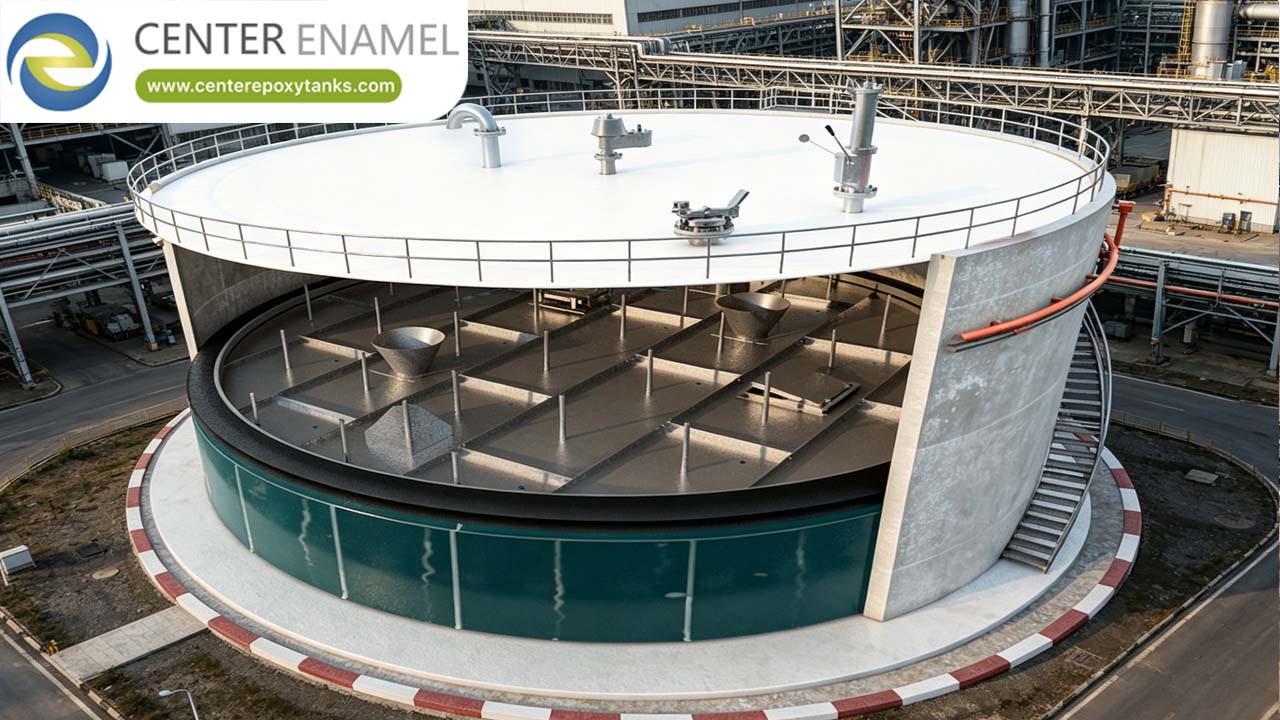
Engineering Guide to ASCE 7 Internal Floating Roofs (IFR)
In high-stakes industrial storage, the internal floating roof (IFR) is the primary line of defense against both environmental contamination and fire hazards. However, a floating roof is only as reliable as the structural engineering data governing its response to external stresses. By integrating ASCE 7 environmental load criteria with API 650 Appendix H mechanical standards, engineers ensure that IFR systems remain stable, operational, and code-compliant—even under seismic stress.
1. The Role of ASCE 7 in IFR Seismic Design
The most significant impact of ASCE 7 on internal floating roof design is Seismic Analysis. When a storage tank experiences earthquake-induced ground acceleration, the stored liquid undergoes "sloshing" (hydrodynamic movement).
Hydrodynamic Sloshing Forces
Under ASCE 7, the liquid inside a tank is analyzed in two modes:
1. Impulsive Component: The liquid mass that moves in unison with the tank shell.
2. Convective (Sloshing) Component: The upper liquid mass that oscillates due to low-frequency waves.
These forces create a vertical uplift and lateral pressure on the IFR. If the IFR is not designed per ASCE 7 site-specific seismic criteria, the roof may bind against the tank shell or be damaged by the liquid waves, leading to seal failure and vapor release.
2. Key Structural Mandates for IFR Safety
To meet ASCE 7 and API 650 requirements, IFR design must account for the following structural benchmarks:
Buoyancy Reserve (2.0x Safety Factor)
The IFR must be engineered with a flotation reserve capable of supporting at least twice (2.0x) the total dead weight of the roof structure, including all peripheral seals, support legs, and instrumentation. This ensures the roof remains buoyant during standard operations and during potential emergency scenarios caused by structural disturbances.
Puncture Survival Contingency
The IFR must be designed to remain fully afloat even if the primary center deck and any two adjacent structural compartments are breached. In seismic zones determined by ASCE 7, this "redundant buoyancy" is critical to preventing the roof from sinking if the tank experiences shell deformation.
Adjustable Support Legs (Maintenance & Load Setting)
The IFR is equipped with heavy-duty pipe support legs. These serve two functions:
● Operating Position: The legs are set to maximize the tank’s usable capacity.
● Maintenance Position: During out-of-service cleaning or inspection, the legs are set to a "high-leg" position (typically 2 meters or 7 feet), providing safe clearance for maintenance crews entering the tank.
3. Vapor Suppression and Emission Control
ASCE 7-compliant IFRs are central to emission control strategies. By maintaining a physical barrier between the liquid and the tank’s internal atmosphere, they prevent the formation of a flammable vapor-air mixture.
● VOC Suppression: Properly installed, an IFR achieves up to 99% suppression of VOC emissions, drastically reducing the environmental impact of storage facilities.
● Rim Seal Integrity: The perimeter seal (the gap between the IFR and the tank shell) is the most vulnerable point for vapor escape. Engineering these seals to withstand the mechanical "flexing" dictated by ASCE 7 seismic calculations is crucial for long-term emission compliance.
4. Engineering Synergy: Pairing IFRs with Aluminum Domes
The most robust storage configuration pairs an IFR with an ASCE 7-compliant Aluminum Geodesic Dome Roof (ADR).
Integrating an ADR provides a "clear-span" environment (no internal vertical columns). This column-free setup is superior for IFR operation because:
1. Elimination of Obstructions: It removes columns that would otherwise penetrate the IFR, reducing wear on seals.
2. Weather Protection: It shields the IFR from external weather loads, eliminating rainwater drainage failures.
3. Maximum Reliability: It creates a redundant protection layer that ensures the IFR operates in a controlled atmosphere, significantly extending the life of the entire system.
Strategic Asset Protection
Designing an internal floating roof using ASCE 7 criteria is a mandatory strategy for facilities in high-risk zones. By prioritizing structural stability under sloshing/seismic loads and utilizing high-performance materials, operators ensure that their IFR assets provide consistent, code-compliant vapor containment for decades.