Engineering Guide to ASCE 7 External Floating Roofs (EFR)
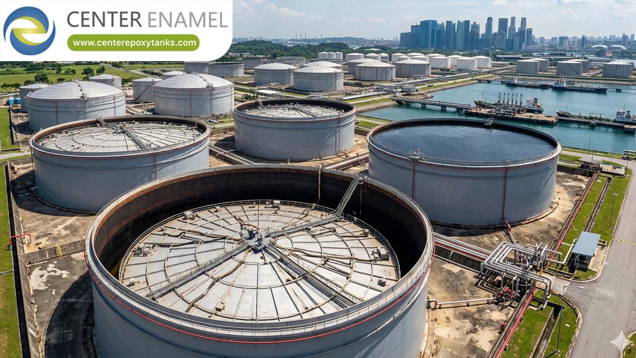
In massive-scale hydrocarbon storage, the External Floating Roof (EFR) is the industry standard for high-volume crude oil and refined product containment. Unlike internal systems shielded by a fixed dome, an EFR is exposed to the full spectrum of environmental energy. To ensure these assets do not fail during a windstorm or seismic event, engineering design must move beyond API 650 mechanical specifications and integrate the rigorous structural load modeling required by ASCE 7.
1. Environmental Load Modeling (ASCE 7)
Because an EFR is open to the atmosphere, it is susceptible to two primary external load vectors defined by ASCE 7: wind uplift and snow accumulation.
Wind Uplift and Pressure Coefficients (C_p)
Wind flowing across the top of an open tank creates a vortex effect that exerts significant upward pressure on the EFR deck. If the deck is not engineered to resist this force, it can lift off the liquid surface, compromising the rim seal and potentially causing structural fatigue.
The design pressure (p) is calculated using the ASCE 7 velocity pressure formula:
Engineers must apply specific pressure coefficients (C_p) to the roof surface. Because EFRs are large-diameter discs, the center of the roof experiences different aerodynamic pressures than the perimeter near the tank shell. ASCE 7-compliant design ensures the structural stiffness of the pontoon matrix is sufficient to counteract this localized lift.
Unbalanced Snow Drifts
In northern climates, snow does not accumulate evenly. Wind-driven drifting creates "unbalanced" loads, where one side of the EFR may bear significantly more weight than the other. ASCE 7 mandates modeling these unbalanced scenarios. If the roof’s structural framework lacks sufficient rigidity, this uneven loading can cause the roof to tilt, inducing mechanical binding against the tank wall—a precursor to structural failure.
2. Seismic Hydrodynamic Sloshing
During a seismic event, the liquid inside an EFR tank acts as a dynamic force. ASCE 7 categorizes this liquid response into two modes:
● Impulsive Mode: The lower mass of the liquid moving with the tank shell.
● Convective (Sloshing) Mode: The upper liquid mass forming low-frequency waves.
ASCE 7 guidelines for hydrodynamic pressure are vital here. The EFR must be designed to withstand the vertical and lateral pressures exerted by these waves. If the IFR/EFR design ignores ASCE 7 seismic site-specific factors, the "sloshing" wave height can exceed the roof’s freeboard, causing the roof to sink or be severely damaged as it impacts the tank’s internal components.
3. Structural Mandates for EFR Stability
To achieve ASCE 7 and API 650 compliance, EFR design must satisfy critical stability benchmarks:
● Buoyancy Reserve (2.0x Factor): The EFR must possess a flotation reserve capable of supporting at least twice (2.0x) the total dead weight of the roof assembly, including peripheral rim seals, drains, and floating instrumentation. This reserve is the "insurance policy" against sinking during extreme ASCE 7 load events.
● Two-Compartment Puncture Survival: The pontoon matrix must be engineered so that if the primary outer rim and any two adjacent structural compartments are breached, the roof will remain level and buoyant.
● Static Dissipation: Because EFRs are subjected to wind and mechanical movement, they must integrate flexible stainless steel bonding cables (shunts) that maintain constant contact with the tank shell to eliminate static spark hazards.
Technical Performance Profile Matrix
Engineering Metric | Non-Compliant EFR | ASCE 7-Compliant EFR |
Wind Stability | Vulnerable to deck lift/vibration | Aerodynamically stable under C_p loads |
Snow Handling | Risk of tilting/mechanical binding | Rigid matrix prevents buckling |
Seismic Response | Failure during hydrodynamic sloshing | Engineered for convective wave forces |
Seal Integrity | Failure due to shell ovality/binding | Resilient seals accommodate shell movement |
4. Engineering Synergy: The Clear-Span Upgrade
The ultimate engineering strategy for maximizing EFR lifespan and performance is to eliminate the external load variable entirely by converting the EFR into an Internal Floating Roof (IFR) sheltered by an ASCE 7-compliant Aluminum Geodesic Dome (ADR).
Benefits of this conversion:
1. Elimination of External Loads: The dome handles the wind, snow, and rain, meaning the floating deck no longer needs to be designed for ASCE 7 atmospheric load vectors.
2. Seal Longevity: Without wind-induced vibration, the rim seals experience significantly less wear, ensuring 99%+ VOC suppression for decades.
3. Maintenance Efficiency: It removes the need for complex, failure-prone primary roof drainage systems (articulated pipes) required on open-top EFRs.
Engineering for Resilience
Engineers specifying External Floating Roofs must look beyond simple buoyancy and analyze the structural environment. By applying ASCE 7 seismic and load-path modeling to the mechanical design of the EFR, facility operators can guarantee that their storage assets remain safe, compliant, and efficient, regardless of external environmental stressors.