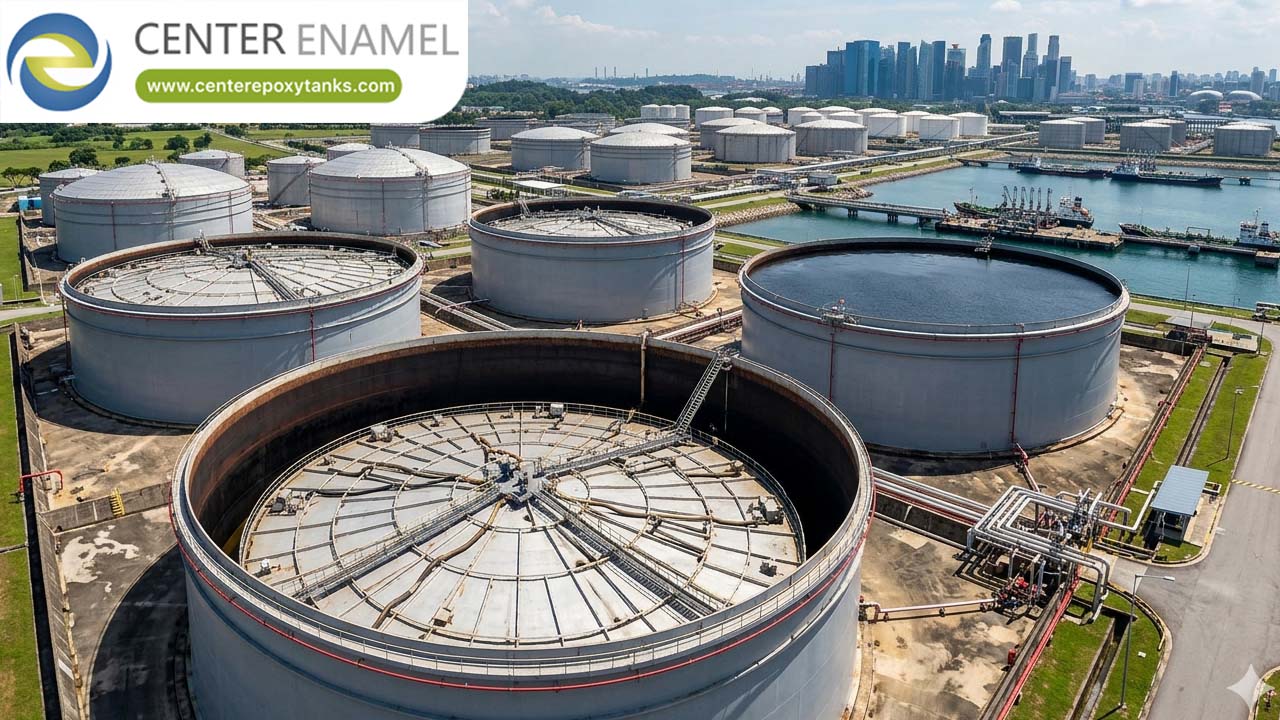
Engineering ASCE 7-Compliant Floating Roof Systems
In large-scale hydrocarbon storage and environmental containment, a floating roof’s reliability is predicated on its ability to handle dynamic energy. While API 650 provides the mechanical blueprints for construction, ASCE 7 provides the structural load criteria necessary to ensure those blueprints survive the reality of the installation site.
Engineers must reconcile the buoyancy requirements of floating decks with the unpredictable nature of wind uplift, snow drifts, and earthquake-induced hydrodynamic waves. This guide details the integration of ASCE 7 criteria into floating roof design.
1. Seismic Design: Calculating Hydrodynamic Sloshing
The most vital application of ASCE 7 to floating roof design is the modeling of hydrodynamic sloshing. During an earthquake, the liquid stored in the tank does not remain static; it interacts with the tank wall and the floating roof in two primary modes:
● Impulsive Mode: The liquid mass moving in unison with the tank shell.
● Convective Mode (Sloshing): The upper liquid mass that oscillates due to low-frequency waves.
ASCE 7 mandates the calculation of these forces to determine the wave amplitude (dc). If an IFR or EFR is not designed to handle these calculated wave heights, the roof deck may experience mechanical binding. In this scenario, the deck catches on the tank wall or its own support legs, potentially leading to seal failure or structural puncture. Seismic-compliant roof design requires calculating the base shear force and pressure distributions to ensure the deck’s rim seals and support structures have sufficient flexibility to absorb this energy.
2. Wind Uplift and Pressure Coefficients (Cp)
For External Floating Roofs (EFRs), ASCE 7 is the primary standard for wind-load design. Wind flowing across an open-top tank creates a vortex effect that exerts intense uplift pressure on the roof deck.
Because the roof deck is a flat or slightly sloped surface, external pressure coefficients must be carefully modeled. A design that fails to account for ASCE 7 wind uplift can suffer from "deck lift," where the roof separates from the product surface, causing seal instability and massive VOC emissions.
3. Structural Integrity and Load Resilience
To achieve ASCE 7 compliance, floating roofs must satisfy rigorous structural benchmarks:
● Buoyancy Safety Factor (2.0x): The roof must maintain stable flotation with a reserve capable of supporting at least twice the dead weight of the roof assembly, ensuring the deck stays afloat even if localized structural damage occurs due to seismic shifting.
● Two-Compartment Puncture Survival: The design must demonstrate that the deck will remain level and buoyant even if the primary outer rim and two adjacent internal compartments (or honeycomb panels) are breached.
● Static Dissipation: Because ASCE 7 wind and seismic events can cause rapid roof movement, grounding systems must be designed to maintain constant contact with the tank shell, preventing static spark ignition during turbulent events.
Technical Performance Profile Matrix
Engineering Metric | Non-Compliant Design | ASCE 7-Compliant Design |
Seismic Response | Risk of deck binding/sinking | Engineered for sloshing/hydrodynamic movement |
Wind Resilience | Vulnerable to deck lift (EFR) | Aerodynamic stability via pressure modeling |
Seal Integrity | Failure during shell deformation | Resilient rim seals (accommodates shell ovality) |
Operational Lifespan | Reduced by fatigue/stress | Maximized via load-path optimization |
4. Engineering Synergy: The Clear-Span Dome Integration
Modern engineering best practices dictate that the most effective way to protect a floating roof from the external load variables defined by ASCE 7 is to enclose the system.
By installing a clear-span Aluminum Geodesic Dome (ADR) over an Internal Floating Roof, operators achieve a dual-layer defense:
1. Elimination of External Loads: The dome takes the full brunt of wind and snow loads, shielding the floating roof from the atmospheric variables otherwise governed by ASCE 7.
2. Column-Free Synergy: Removing internal vertical columns prevents the IFR from binding, which is a major point of failure during seismic events.
3. VOC and Emission Control: This configuration creates a "closed-loop" storage environment that maximizes VOC suppression to 99%+.
Strategic Asset Resilience
Designing a floating roof is not merely about buoyancy—it is about structural energy management. By utilizing ASCE 7 to calculate the seismic sloshing and wind uplift forces, and by pairing systems with clear-span coverage, facilities can ensure their storage infrastructure remains resilient, compliant, and operational through decades of service.