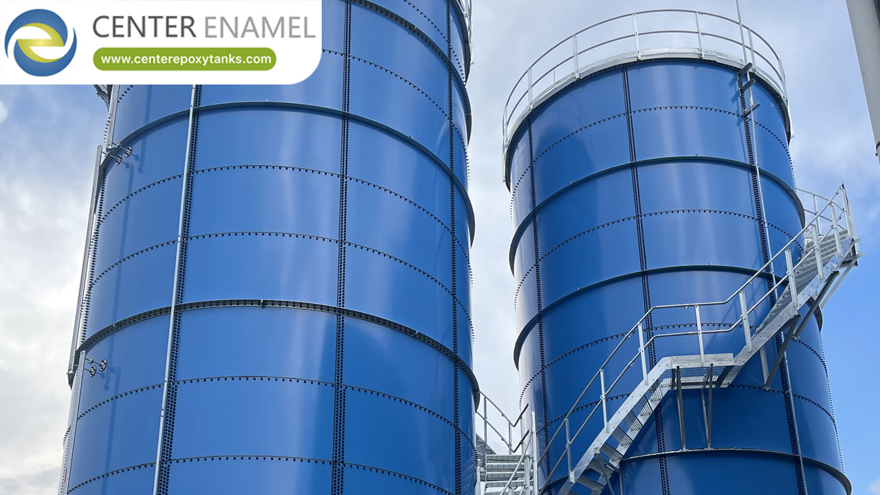
Data Center Chilled Water Storage Tank: Capacity, Layout and Thermocline Management
Once a data center chilled water storage tank is specified, the next questions are about capacity planning and layout: how much real storage do you get, how do you arrange one or more tanks on the campus, and how do you keep the thermocline sharp? This article addresses those planning decisions.
Usable capacity is not the geometric volume - it is the cold fraction preserved by a thin thermocline, typically 85-95% of total. Layout choices (one large tank vs several smaller) trade footprint, redundancy, and erection logistics. Thermocline management - via low-Froude diffusers and multi-height sensing - protects that usable fraction throughout charge and discharge.
Capacity: Geometric vs Usable
The thermocline occupies a finite band of the tank; only the fully cold layer below it is dispatchable cooling. A sharp thermocline (0.5-1.5 m) preserves most of the volume; a thick, wandering one can waste 20% or more.
Capacity planning should therefore specify usable m3 at a target Delta-T, not just tank height and diameter.
Single Large Tank vs Tank Farm
One large tank minimizes shell surface per volume and is simplest to control, but concentrates risk and needs a large clear footprint. Several smaller tanks add redundancy and fit awkward sites, at higher total surface and complexity.
For campuses phasing construction, a tank farm lets capacity grow with IT load - a common data-center pattern.
Thermocline Management in Practice
Diffuser velocity is the primary control lever: keeping the Froude number low prevents jet entrainment that destroys stratification. Combined with stratified sensing and gentle mode transitions, the thermocline stays stable across thousands of cycles.
Technical Specifications
Parameter | Specification |
Usable factor | 0.85-0.95 of volume |
Thermocline thickness | 0.5-1.5 m target |
Diffuser Froude | < ~1 (low velocity) |
Sensing | Multi-height temperature |
Layout option A | Single large tank |
Layout option B | Tank farm (phased) |
Redundancy | Per-tank isolation |
Shell | Atmospheric stratified |
Material | GFS / stainless / welded |
Standard | AWWA D103, ISO 28765 |
Verified Tank Engineering Reference
Center Enamel's multi-tank installations - such as a 2023 Saudi Arabian project of five GFS tanks at 24.06 m diameter and 11,020 m3 - illustrate the ability to deliver a coordinated tank farm, relevant when a data center phases TES or buffer capacity. Capability evidence, not a DC project.
Project location | Saudi Arabia |
Application | Municipal wastewater |
Tank type | GFS (Glass-Fused-to-Steel) bolted tank |
Scale | 5 unit(s), φ24.06*4.85(H) |
Total volume | 11,020 m3 |
Year | 2023-12 |
Note | Cited as manufacturing-capability evidence, not a data-center project. |
Center Enamel Capability
Center Enamel's bolted-tank system is well suited to tank farms: standardized panels allow multiple shells of consistent quality on one site, and erection can be sequenced to match campus build-out. QA is under ISO 9001 with AWWA D103 / ISO 28765 construction.
For pressurized duties on the same campus, ASME Section VIII vessels are available from the same engineering and quality system.
Frequently Asked Questions
Q: What is usable capacity?
A: The cold fraction of the tank preserved below a thin thermocline - usually 85-95% of geometric volume.
Q: One big tank or several?
A: One tank is simpler and lower surface area; a tank farm adds redundancy and phased growth at higher complexity.
Q: How thick should the thermocline be?
A: Aim for 0.5-1.5 m; thicker bands waste usable storage.
Q: What controls thermocline sharpness?
A: Low-Froude diffusers and gentle flow transitions; multi-height sensors verify layer position.
Q: Can capacity grow with the campus?
A: Yes - a tank farm lets TES or buffer volume be added as IT load grows.
Q: Which standard for the shells?
A: Bolted steel tanks to AWWA D103 and ISO 28765; pressurized vessels to ASME VIII.
Capacity and layout decisions decide how much of the tank you can actually use. Plan in usable cubic meters, choose single vs farm by site and redundancy needs, and protect the thermocline with disciplined diffuser and control design.
Suggested Next Step
Tell us your campus phasing and footprint - we will lay out a single or multi-tank TES configuration with usable-capacity numbers.