Comprehensive Installation Guide: API 650 Internal Floating Roofs (IFR)
The installation of an API 650 Internal Floating Roof (IFR) is a high-precision mechanical workflow that directly influences a facility's emission control efficiency and operational safety. Governed by API 650 Appendix H, the assembly of an IFR requires meticulous geometric leveling, strict torque management, and flawless peripheral seal deployment to ensure smooth tracking along the tank shell.
As a global premier manufacturer of industrial containment systems since 2008, Shijiazhuang Zhengzhong Technology Co., Ltd (Center Enamel) defines the professional standard for code-compliant storage infrastructure. This technical guide outlines the step-by-step Standard Operating Procedure (SOP) for installing a modular internal floating roof inside a fixed-roof storage tank.
1. Pre-Installation Preparation and Safety Protocols
Before transferring components into the tank, comprehensive site and safety clearances must be satisfied.
● Tank Cleanliness: The tank floor must be completely clean, dry, and free of construction debris, weld splatter, or residual chemical sludge.
● Atmospheric Verification: For brownfield retrofits, follow strict confined-space entry protocols. Ensure the internal headspace is thoroughly gas-freed, continuously monitored, and certified safe for entry.
● Staging Components: Organize pre-fabricated modular panels, structural pontoons, perimeter rim seals, and support legs in a clean staging area outside the tank access manway.
2. Installation Workflow: The Step-by-Step Assembly
The following sequence applies to the mechanical erection of a standard modular aluminum or stainless steel skin-and-pontoon or full-contact panel IFR.
Phase 1: Support Leg and Rim Framework Grid
1. Layout Grid: Map out the exact positioning of the temporary/permanent support legs directly on the tank floor according to the manufacturer’s engineered layout drawings.
2. Leg Setting: Install the support legs (set at the designated design maintenance height, typically 1.5 to 2 meters) and secure the primary outer rim channel.
3. Perimeter Check: Verify the roundness of the outer rim framework relative to the internal tank shell wall, ensuring the uniform expansion gap matches engineering tolerances.
Phase 2: Structural Matrix and Buoyancy Unit Assembly
1. Lattice Erection: Begin connecting the cross-beam structural struts to the outer rim channel, working inwards to form the rigid grid matrix.
2. Pontoon Positioning: For non-contact roofs, align the sealed structural pontoons beneath the grid framework. Clamping brackets must be torqued precisely to lock the buoyancy units firmly into position.
3. Leveling Audit: Use a precision laser level across the entire exposed skeletal matrix. Structural deflection or leveling imbalances will cause the roof to bind or tilt during future filling cycles.
Phase 3: Deck Skin Deploying and Fastening
1. Panel Laydown: Lay out the modular aluminum deck sheets or full-contact honeycomb panels across the top of the structural framework.
2. Seam Sealing: Apply continuous beads of product-compatible, UV-resistant elastomeric sealant between all overlapping panel joints.
3. Batten Bar Clamping: Secure the panel seams using heavy-duty batten bars or clamping strips. Tighten all structural fasteners to the project's specified torque values using calibrated torque wrenches to guarantee a vapor-tight deck barrier.
Phase 4: Peripheral Rim Seal and Accessory Integration
1. Rim Seal Mounting: Install the engineered peripheral rim seal system (e.g., mechanical shoe, wiper, or foam-filled resilient seal) along the perimeter gap. Ensure continuous, flexible surface contact with the internal tank shell wall.
2. Anti-Rotation Systems: Secure the anti-rotation guide poles or stainless steel cables to prevent the floating deck from spinning or shifting during fluid turbulence.
3. Grounding and Venting: Install flexible electrical bonding cables (shunts) from the IFR frame to the tank shell to ensure continuous static electricity dissipation. Integrate the automatic breather vents, which relieve air pressure when the roof lands on its legs during drainage.
3. Quality Control & Commissioning Standards
Before the tank is locked down and commissioned for liquid storage, the installation must pass a rigorous quality audit.
● Joint Tightness (Vacuum Box Test): Perform a localized vacuum box test or a meticulous bubble leak test along the sealed panel seams to ensure complete vapor suppression.
● Flotation Clearance Verification: Inspect the peripheral seal compression around the entire $360^circ$ radius of the tank shell, ensuring there are no binds, gaps, or puckered edges.
● Freedom-of-Movement Check: Where feasible, perform a water-float test by gradually filling the tank to observe the roof’s vertical travel tracking, confirming it glides smoothly without catching or twisting.
Modular Installation Summary Table
Installation Phase | Core Mechanical Activity | Quality Requirement / Tolerance |
Phase 1: Foundation | Layout grid & set support legs | Structural perimeter gap must be uniform. |
Phase 2: Skeletal Framework | Assemble lattice & mount pontoons | Laser-verified level across the matrix diameter. |
Phase 3: Deck Enclosure | Lay panels, apply sealant & torque clamps | Vapor-tight seams via strict fastener torque control. |
Phase 4: Optimization | Fit rim seals, bonding cables & vents | Continuous seal contact; verified static grounding path. |
System Synergy: Dome Roof and IFR Alignment
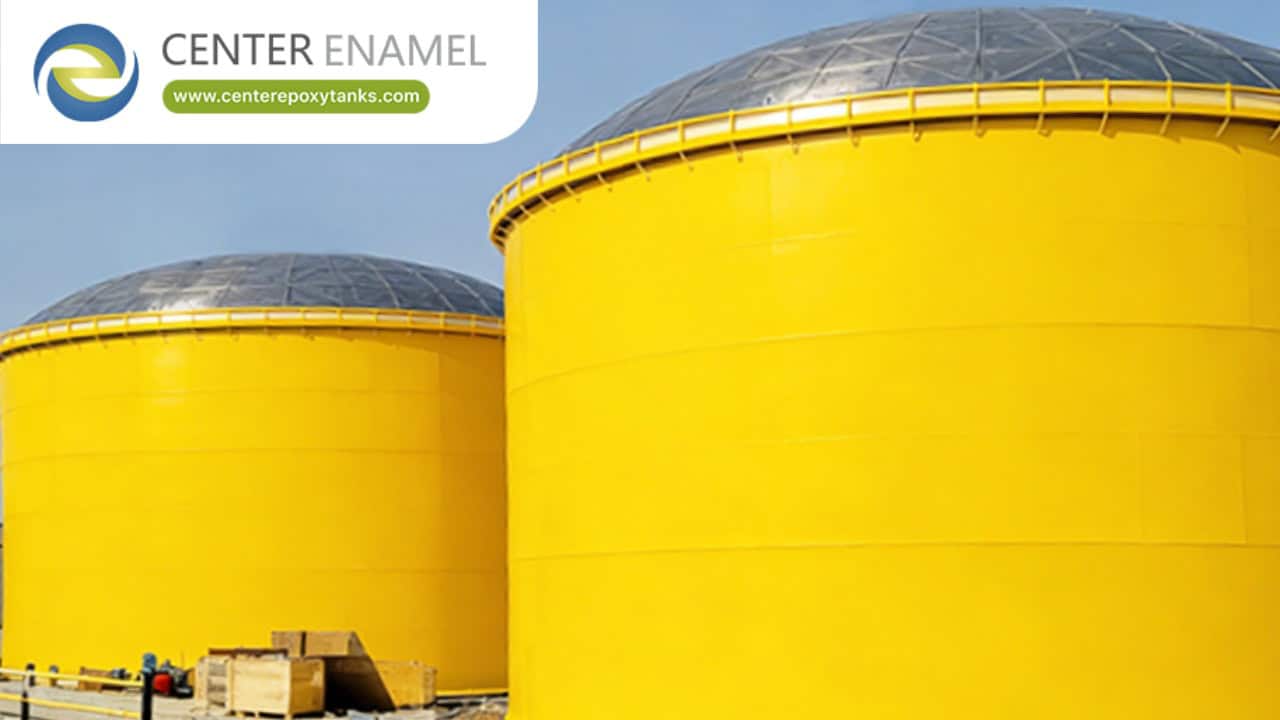
The installation timeline and long-term mechanical reliability of an internal floating roof improve dramatically when paired with a clear-span fixed cover, such as an aluminum geodesic dome roof. Traditional steel fixed roofs rely on internal vertical support columns that require custom sleeves, penetrations, and complex cutouts through the floating deck.
By eliminating internal vertical columns entirely, a clear-span dome roof leaves the internal tank environment completely unobstructed. This permits a rapid, uninterrupted modular IFR layout and eliminates column friction points, preventing rim seal abrasion and maximizing the lifetime performance of the containment asset.
Engineering for Lifelong Efficiency
Adhering to a disciplined, code-compliant installation workflow ensures that an API 650 Internal Floating Roof delivers maximum emission reduction, regulatory compliance, and fire hazard mitigation over its operational lifespan. Partnering with a manufacturer capable of delivering fully pre-fabricated, precision-machined kit components minimizes field error and accelerates project completion.
Center Enamel provides full-scale technical documentation, precision engineering, and comprehensive installation supervision for integrated tank and roofing systems globally. Contact our specialized engineering team today to review your project's technical specifications and installation blueprint.