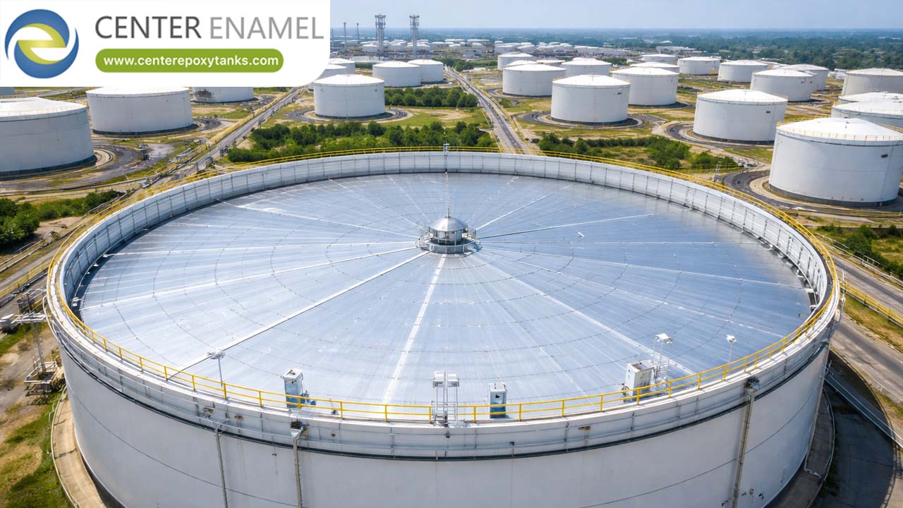
Engineering Guide to API 650 Appendix H: Internal Floating Roofs
In the bulk liquid storage industry, the internal floating roof (IFR) is the primary engineering solution for mitigating evaporative loss and preventing the formation of explosive vapor mixtures. API 650 Appendix H serves as the "Rulebook" for these systems. Adherence to these mechanical standards is not optional; it is the baseline for global compliance and operational safety.
Whether you are designing a new tank or retrofitting an existing asset, understanding Appendix H is fundamental to ensuring your IFR will perform consistently for a 20+ year service life.
1. The Core Mechanical Pillars of Appendix H
Appendix H is structured to ensure that an IFR operates as a dynamic component of the tank, rather than a static one. The following mechanical pillars are non-negotiable:
A. The Buoyancy Mandate
The most critical safety feature of any IFR is its ability to remain afloat. API 650 Appendix H mandates that the floating roof must have a minimum buoyancy reserve equal to 2.0x the total weight of the roof (including all attachments, seals, and instrumentation).
● Puncture Survival: The design must be "fail-safe." It must maintain positive buoyancy even if the peripheral rim and any two adjacent internal compartments are punctured or breached.
B. Rim Seal Architecture
The rim seal is the barrier between the floating deck and the tank wall. Appendix H specifies that the seal must:
● Minimize the gap between the deck and the shell to prevent vapor escape.
● Accommodate shell "ovality" (slight non-circular distortion of the tank shell).
● Be compatible with the stored product’s chemical properties to prevent seal degradation.
C. Electrical Continuity (Grounding)
Because IFRs move vertically as the tank is filled or emptied, they can generate static electricity. Appendix H requires the installation of flexible stainless steel shunts (bonding cables) to maintain constant electrical continuity between the roof and the tank shell. This is a critical fire-prevention measure.
2. Technical Design Requirements Summary
Design Component | API 650 Appendix H Requirement |
Buoyancy Safety Factor | 2.0x Total Dead Weight |
Puncture Integrity | Must float if 2 compartments breached |
Annular Gap | Must allow for shell ovality tolerances |
Grounding | Continuous electrical shunts required |
Support Legs | Adjustable (Operating vs. Maintenance positions) |
3. Structural Integrity and Load Paths
Appendix H does not just dictate buoyancy; it governs the structural rigidity of the deck. This is particularly important for avoiding mechanical "binding"—the phenomenon where the roof gets stuck against the tank wall due to misalignment or seismic shell deformation.
Adjustable Support Legs
IFRs are equipped with heavy-duty pipe support legs. These serve a dual purpose mandated by the standard:
1. Operating Position: Sets the roof height to maximize the tank's liquid storage capacity.
2. Maintenance (High-Leg) Position: Provides a safety clearance (typically 2 meters or 7 feet) for personnel to enter the tank for cleaning and inspection.
4. Why Compliance Matters
Non-compliance with Appendix H creates immediate operational risks:
● Emission Fines: Regulatory bodies (like the EPA or equivalent local agencies) mandate specific VOC suppression rates. An IFR that does not meet Appendix H seal gap requirements will likely fail emissions testing.
● Operational Downtime: A roof that binds or sinks due to inadequate buoyancy engineering can take a tank offline for weeks, costing significant revenue and requiring costly repairs.
● Fire/Safety Hazards: Improperly grounded IFRs or those with inadequate seal designs can lead to "rim fires" if a lightning strike or static discharge occurs.
Engineering for Reliability
API 650 Appendix H is the foundational standard for Internal Floating Roof design. By strictly adhering to its requirements for buoyancy, seal integrity, and electrical continuity, engineers can ensure that their storage assets remain safe, compliant, and efficient.
For critical infrastructure, the recommendation is clear: treat Appendix H not as a minimum guideline, but as the mandatory floor for your engineering specifications.
Does your team require a technical review of how specific tank diameters or shell tolerances affect the seal-gap requirements outlined in Appendix H?