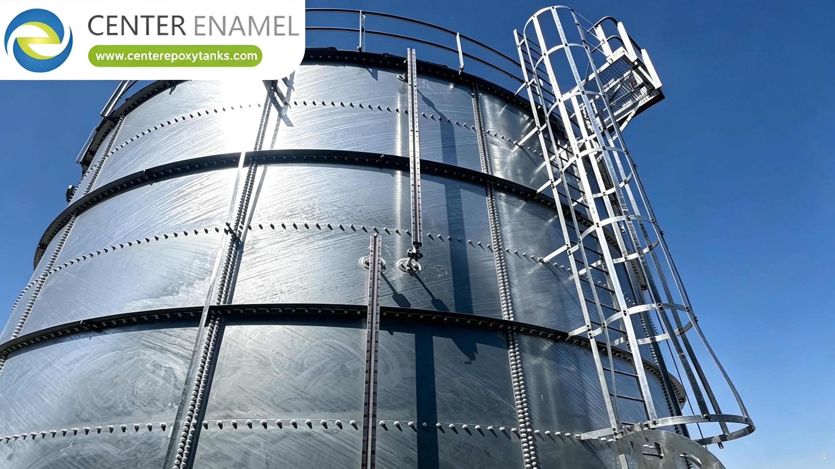
Data Centre Cooling Water Storage Tank: Water Quality, Biocide And Maintenance
A data centre cooling water tank stays serviceable only while the loop chemistry is controlled. Corrosion, scaling and microbiological growth are governed by the treatment regime and the sampling plan, and the tank lining is protected by the same programme. Inspect and clean the tank on a fixed schedule, and treat water quality as a continuous operating duty, not a fill-time decision.
Introduction
Cooling water is not inert. The moment a data centre cooling loop fills, the water starts reacting with the metal it touches, with the air above it and with everything the air and the make-up supply carry in. For a data centre operator the tank is the buffer that keeps the cooling plant running through a make-up interruption, but it is also the slowest-moving body of water in the system and therefore the place where chemistry problems accumulate before they show up at the chiller.
This article treats water quality as an operating discipline rather than a one-time fill specification. It covers what is actually in the cooling water, the corrosion and scaling mechanisms that govern equipment life, the microbiological growth that biocide programmes exist to control, the treatment regime that keeps the loop within limits, the sampling plan that tells you whether it is working, and the inspection and cleaning the tank itself needs.
Two conventions run through the text. All chemistry limits are stated as operating targets the system standard and your water report set, not as fixed numbers, and the tank lining discussion references AWWA D102 for coating steel water-storage tanks because the tank is part of the same water system the treatment programme protects.
What is in the cooling water
The water you put into a cooling loop is a chemical mixture before it ever reaches the tank. Municipal or well make-up carries dissolved minerals, calcium and magnesium that drive hardness, bicarbonate that governs alkalinity, chloride and sulfate that drive corrosion, and suspended and dissolved solids that affect both deposition and fouling. Open cooling towers then concentrate those constituents as water evaporates, because evaporation removes pure water and leaves the dissolved load behind, so the concentration factor rises until blowdown removes it.
Air drawn through the tower adds oxygen, dust, pollen, airborne bacteria and, in some locations, process or traffic-borne contamination. The make-up source sets the baseline; the tower sets the load on top of it. A water report from the actual supply, not a generic regional average, is the starting point for any treatment decision, because the calcium hardness, the alkalinity, the chloride level and the silica content together decide which scaling and corrosion problems you are controlling for.
Corrosion mechanisms in a cooling loop
Corrosion in a cooling system is mostly electrochemical. Dissolved oxygen at the metal surface drives the reaction, and chloride and sulfate ions break down the passive films that would otherwise slow it, so the same constituents that make a supply aggressive also make it hard to protect. Localised corrosion, including pitting under deposits, does more damage than uniform loss because a small pit penetrates the wall while the average thickness looks fine.
Galvanic effects appear wherever dissimilar metals meet in the presence of an electrolyte, and crevice corrosion forms where flow stagnates or where a gasket or fitting traps water. Temperature and velocity matter: high velocity causes erosion-corrosion at bends and nozzles, low velocity lets deposits settle and shield corrosion underneath. The tank adds a complication because its water turns over slowly, so a chemistry excursion at the tank can persist longer than the same excursion at a fast-moving point in the loop.
Scaling and deposition
Scaling is the reverse problem: dissolved minerals leave solution and form a solid layer on heat-transfer surfaces, and the layer insulates the surface it coats. Calcium carbonate is the usual offender, precipitated when the calcium, the alkalinity and the temperature combine past the solubility limit; calcium sulfate and silica scale appear where those species are high. The driving term is the concentration factor, the ratio of circulating to make-up concentration, because every constituent the blowdown does not remove is multiplied by it.
Deposition is broader than scaling. Suspended solids, corrosion products, microbiological slime and airborne debris all settle, and they act as nucleation sites that make scaling worse and as shields that let corrosion run underneath. The control levers are the blowdown rate, which sets the concentration factor, the pH, which sets the calcium carbonate equilibrium, and the dispersant programme, which keeps precipitated material in suspension long enough to be blown down. A loop run at too high a concentration factor saves water but pays for it in scale.
Microbiological growth and its consequences
Cooling water is warm, aerated and nutrient-rich, which is exactly the condition that supports microbial growth, and the problem is not cosmetic. Bacteria, including Legionella and sulfate-reducing species, form biofilms on every wetted surface, and the biofilm protects the organisms inside it from the very biocide meant to kill them. Sulfate-reducing bacteria generate hydrogen sulfide and drive severe localized corrosion under the slime layer.
The operational consequences are real: reduced heat transfer through biofilm insulation, increased pressure drop from partial blockage, fouling of strainers and nozzles, and a standing health risk at an open tower that discharges aerosol. A microbial excursion is also self-reinforcing, because the slime it leaves behind is the next colony's footing. The tank matters here because it is the largest quiet volume in the system, and quiescent water with settled solids is where biofilms establish first if the programme lapses.
The treatment regime
A cooling water treatment programme targets all three failure modes at once. A corrosion inhibitor forms a protective film on metal; common choices include zinc, phosphonate, molybdate or polymeric filming amines, selected against the metal in the system and the discharge limits at the site. A scale and deposit control agent, usually a phosphonate or a polymer dispersant, holds precipitated solids in suspension so blowdown removes them. An oxidising biocide, most often chlorine or bromine, provides a baseline kill, backed by a non-oxidising biocide on a shock schedule to penetrate established biofilm.
The programme is set by the water report and the concentration factor you choose. Dosing is normally continuous for inhibitor and dispersant and intermittent for biocide, and the make-up flow or the circulation flow meters the dose so the active concentration tracks system demand. The tank itself is usually not dosed directly; it is protected by the chemistry of the loop it shares, which is why the lining and the treatment programme are the same story told from two sides.
Sampling and monitoring plan
A treatment programme you cannot measure is a treatment programme you are guessing at. The monitoring plan fixes what you test, where you sample and how often, and it is built around the variables that move first: pH, conductivity (a proxy for concentration factor), calcium hardness, alkalinity, corrosion inhibitor residual, and a microbial count such as heterotrophic plate count with a Legionella test where the risk assessment calls for one.
Sample at a representative circulating point and at the make-up, not only at the tank, because the tank is the last place a chemistry change shows up. Frequency depends on system stability: a stable loop may be weekly, an unstable or seasonal one daily. Log every result against the control range so a trend is visible before a limit is breached, and keep the records because they are the evidence that the programme was working when a regulator, an insurer or an internal audit asks. Side-stream monitoring and corrosion coupons give an independent check that the online numbers miss.
Tank inspection and cleaning
The tank needs its own inspection and cleaning rhythm because it is the slowest-moving body of water and the one most likely to accumulate sediment. A visual internal inspection at least annually checks the lining for blistering, cracking or disbondment, the floor for accumulated sludge, the inlet and outlet for erosion, and the roof and seal for intrusion that lets contamination in. Corrosion coupons or a UT thickness survey track metal loss where the liner is breached.
Cleaning follows inspection when sludge or biofilm is present. Drain to a permitted point, remove settled solids, wash the surfaces, and confirm the lining condition before refill. The cleaning interval is set by what the inspection finds, not by a fixed calendar alone: a dusty site or a high-organic make-up source needs more frequent attention. The tank's coating, where applied, is the last line of defence the treatment programme relies on, and AWWA D102 governs coating steel water-storage tanks, so the coating specification and the inspection method should reference it.
Linking water quality to the tank's condition
The through-line of this article is that the tank lining and the loop chemistry are one system. Good treatment keeps the water non-scaling and non-corrosive, which is exactly the condition the lining is designed to survive; poor treatment lets the water attack the substrate the moment the coating has a holiday or a crack. The tank inspection then becomes a water-quality report: sludge points to inadequate blowdown, pitting points to chloride or microbiological attack, and disbonded coating points to a programme that ran out of margin.
Designing the two together pays off. Specify the tank lining for the water chemistry you actually have, size the make-up and blowdown so the concentration factor stays where the programme can hold it, and write the inspection findings back into the treatment adjustment. A data centre that treats water quality as an operating duty, with a sampling plan it follows and a tank it inspects on schedule, protects the cooling plant and the storage asset with the same routine.
Cooling Loop Condition vs Control Method
Loop condition | Controlling parameter | Typical control method | Failure if unmanaged |
Corrosion | Dissolved O2, Cl-, SO4- | Inhibitor film (phosphonate/molybdate) | Pitting, wall penetration |
Scaling | Concentration factor, pH, Ca | Blowdown + dispersant | Insulated heat-transfer surfaces |
Deposition | Suspended solids, slime | Dispersant, filtration | Fouling, blockage |
Microbial | Temperature, nutrients, O2 | Oxidising + shock biocide | Biofilm, Legionella risk |
Cooling Water Sampling Plan
Parameter | Sample point | Frequency | Action limit basis |
pH | Circulating + make-up | Weekly (daily if unstable) | System standard range |
Conductivity | Circulating | Weekly | Concentration-factor proxy |
Calcium hardness | Circulating | Weekly | Scaling risk |
Inhibitor residual | Circulating | Weekly | Programme setpoint |
HPC / Legionella | Circulating | Per risk assessment | Site risk assessment |
Project Reference
The project reference records a chemical process water project with a total storage volume of 11609 m3, completed in 2024. The published record does not give the site location or the application, and the tank diameter and height are not published. The reference is included to show scale and the construction type in service. It is a limited reference because the recorded application differs from this article's subject, and it is not offered as evidence of any treatment outcome.
Location | Service | Total Storage Volume | Year |
location not stated in source | application not stated in source | 11609 m3 total storage volume | 2024 |
About Center Enamel
Center Enamel (Shijiazhuang Zhengzhong Technology Co., Ltd.) designs and fabricates bolted steel storage tanks, welded steel tanks, fusion-bonded epoxy tanks, galvanized tanks, stainless steel vessels, pressure vessels, aluminum geodesic dome roofs and floating roofs. The company has more than 30 years of production experience and has supplied equipment to projects in more than 100 countries. Aluminum geodesic dome roofs are designed and fabricated to API 650 Appendix G, AWWA D108, the Aluminum Design Manual, ASCE 7 and IBC, and the company developed and exported a 72 m diameter aluminum dome roof in 2023. Engineering, fabrication, coating, quality control and site service are handled as one scope, which is why the drawings, the calculation basis and the delivered hardware can be reconciled against each other.
Frequently Asked Questions
What water quality does a cooling loop need?
A cooling loop needs make-up water whose hardness, alkalinity, chloride, sulfate and silica are known from a site water report, held within operating limits by the blowdown and treatment programme. The control targets, pH, conductivity as a concentration-factor proxy, calcium hardness and inhibitor residual, are set by the system standard and the water chemistry, not by a single fixed number. The tank shares that water, so its lining is specified against the same chemistry the loop is treated for.
What causes corrosion in a cooling water system?
Corrosion is mainly electrochemical, driven by dissolved oxygen with chloride and sulfate ions breaking down the protective passive film, which produces pitting and crevice attack rather than even loss. Galvanic effects appear at dissimilar-metal joints, and erosion-corrosion appears at high-velocity bends and nozzles. The tank compounds this because its water turns over slowly, so a chemistry excursion persists there longer than at a fast-moving point in the loop.
How is scaling controlled?
Scaling is controlled by holding the concentration factor, the ratio of circulating to make-up concentration, within the range the treatment programme can hold, because evaporation concentrates dissolved minerals while blowdown removes them. pH control sets the calcium carbonate equilibrium, a phosphonate or polymer dispersant keeps precipitated solids in suspension, and adequate blowdown carries them out. Running the loop at too high a concentration factor to save water trades directly into scale on heat-transfer surfaces.
Is biocide treatment necessary in a closed loop?
An open cooling tower absolutely needs biocide, because warm aerated water with airborne nutrients supports biofilm and, where the risk assessment requires, Legionella; a non-oxidising shock alongside the oxidising baseline penetrates established slime. A genuinely closed loop, with no tower and negligible make-up, carries far lower biological risk and may need only periodic preservation, but many systems labelled closed still take make-up or air, so the biocide decision follows the actual exposure, not the label.
What should be sampled and how often?
Sample pH, conductivity, calcium hardness, alkalinity, corrosion-inhibitor residual and a microbial count at a representative circulating point and at the make-up, not only the tank, because the tank shows change last. Stable loops may be weekly, unstable or seasonal ones daily. Log every result against its control range so a trend is visible before a limit is breached, and keep the records as evidence for audit and insurance review.
How often should the tank be inspected and cleaned?
Inspect the tank internally at least annually for lining condition, floor sludge, inlet and outlet erosion and roof intrusion, with corrosion coupons or UT where the liner is breached. Clean when inspection finds sludge or biofilm: drain to a permitted point, remove solids, wash and confirm the lining before refill. The interval follows what inspection finds, so a dusty site or high-organic make-up source needs more frequent attention than a clean one.
How does water quality affect the tank lining?
The lining is the last defence the treatment programme relies on, so water quality decides how long it lasts. Aggressive water, high chloride, low pH or active microbiological growth, attacks the substrate the instant the coating has a holiday or a crack, and the inspection then reads as a water-quality report: sludge means weak blowdown, pitting means chloride or biology, disbonded coating means lost margin. Good chemistry and a sound lining are the same protection seen from two sides.
Conclusion
Water quality in a data centre cooling loop is an operating duty with a beginning, a monitoring plan and an inspection record, not a fill-time decision that is forgotten until the chiller complains. The corrosion, scaling and microbiological mechanisms are well understood, and the programme that controls them also protects the tank that stores the water, so the lining and the chemistry are one system to manage together.
The practical routine is short: a water report that sets the limits, a treatment regime matched to it, a sampling plan you actually follow, and a tank you inspect and clean on a schedule the inspection sets. Send us the duty, the water report and the site constraints, and we will return a tank and lining specification built around the chemistry your loop has to survive, with the inspection method that keeps it serviceable.
Talk To Our Engineering Team
Send the duty, the volume basis, the governing code and the site constraints, and our engineering team will come back with a specification that a supplier can price and a reviewer can approve. We will also tell you plainly when a different tank type or a different scope is the better answer.