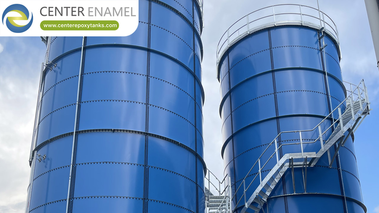
Data Center Buffer Tank: Hydraulic Stability in the Cooling Plant
A data center buffer tank adds thermal and hydraulic volume to the cooling plant so that a small, fast-changing load does not force the chillers to start and stop continuously. It is sized from the minimum system water volume the chiller manufacturer requires - commonly expressed in litres per kW of chiller capacity and stated in the unit data sheet - together with the loop volume already present in pipework, coils and the plant. Where the installed loop volume falls short, a buffer tank supplies the difference and also acts as the hydraulic decoupler between primary and secondary circuits.
Modern chillers modulate efficiently, but they still have a minimum stable capacity. When the load drops below it, or fluctuates faster than the chiller can respond, the machine cycles. Each start costs efficiency and compressor life, and the temperature control at the load becomes uneven.
This article explains why buffer volume solves that problem, how the required volume is established, how the tank connects in a primary-secondary arrangement, and how to specify it. It deals with hydraulic stability, not with thermal storage for load shifting, which is a different duty with a much larger tank.
Technical Explanation
What short cycling does to a cooling plant
Cycling is a mechanical and control problem with measurable consequences:
• Efficiency loss: each start spends time bringing pressures and temperatures into equilibrium, during which the machine is not operating at its design efficiency.
• Wear: compressors and starters accumulate start cycles, which is a maintenance and reliability cost that does not appear in an energy model.
• Temperature instability: supply temperature swings at the load, and at low load the machine may be unable to hold setpoint within the required band at all.
• Control interaction: where several chillers operate in sequence, short cycling can also produce hunting between machines as the controller tries to stabilise.
How buffer volume is determined
The starting point is the chiller manufacturer's minimum system volume requirement, which exists precisely to limit cycling:
• Read the minimum system water volume from the chiller data sheet; it is normally stated in litres per kW of cooling capacity and varies with machine type, refrigerant and control strategy.
• Calculate the volume already available in the loop: pipework, coils, heat exchangers and any existing vessels.
• If the installed volume is below the requirement, the difference is the buffer volume to add.
• Check the control implication: with adequate volume, the chiller can run at minimum capacity while the loop temperature drifts within an acceptable band, and the compressor is not required to stop.
Where the buffer connects
Buffer and decoupler functions can be provided by the same vessel, and the connection arrangement determines whether that works:
• Primary-secondary arrangement: the buffer vessel or the decoupler line separates the constant-flow primary circuit from the variable-flow secondary circuit, preventing flow changes at the coils from disturbing chiller flow.
• Low-loss header: an alternative that provides hydraulic separation without adding much thermal volume; where additional system volume is also needed, a buffer vessel is the better fit.
• Connection points: entering and leaving connections are arranged so that the vessel charges and discharges across the full volume rather than short-circuiting, with internal baffling where necessary.
• Temperature sensing: sensors positioned to reflect the water the control system is responding to, not a stagnant pocket inside the vessel.
Specifying the vessel
A buffer tank is a simple pressure vessel in a controlled environment, and the specification should reflect that:
• Volume: stated as the required added volume, with the calculation basis documented.
• Connection sizes: matched to the loop connections, with low-velocity entries to avoid mixing the stored volume.
• Material and coating: closed-loop water chemistry determines whether a coated steel or stainless vessel is appropriate.
• Insulation: applied where the vessel stores chilled water, since uncontrolled heat gain works against the temperature control the vessel exists to improve.
• Air separation: provision for air removal, since a buffer vessel is a natural collection point for entrained air.
Technical Specifications
Table 1 - Buffer vessel sizing inputs and design decisions
Input | Source | Effect | Design decision |
Minimum system volume | Chiller manufacturer data sheet | Sets the target total loop volume | Amount of buffer volume required |
Existing loop volume | Pipework, coils, heat exchanger take-off | Reduces the buffer volume needed | Whether a vessel is required at all |
Load profile | Building and IT load model | Determines cycling risk and tolerable temperature band | Control strategy and setpoints |
Connection arrangement | Plant layout and hydraulics | Determines whether the vessel also acts as a decoupler | Entering and leaving connection detail |
Water chemistry | Loop treatment programme | Governs vessel material and coating | Coated steel or stainless steel |
Company Expertise
Center Enamel fabricates bolted and welded steel vessels for water and process duty, including coated and stainless steel options, with design and documentation suitable for plant-room equipment where the vessel volume, connection arrangement and insulation must be coordinated with the mechanical design.
As an outstanding containment and cover system provider with decades of industry experience, Center Enamel sincerely expects to establish long-term cooperation with local partners throughout the world and to make continuous contribution to the development of the industry.
Shijiazhuang Zhengzhong Technology Co., Ltd is not only the first manufacturer in China to produce Glass-Fused-to-Steel tanks, but also the most experienced professional bolted tank manufacturer in Asia. The engineering, design, product testing and quality system of Center Enamel Glass-Fused-to-Steel tanks are in strict accordance with AWWA D103-09, OSHA, ISO 28765, NSF/ANSI 61 and NFPA. By 2023, Center Enamel bolted tanks had been exported to more than 100 countries, including the USA, Australia, Canada, Malaysia, Indonesia, Russia, the UAE, Panama, Brazil and South Africa.
Shijiazhuang Zhengzhong Technology Co., Ltd (Center Enamel) is a professional manufacturer dedicated to the design and fabrication of bolted storage tanks since 2008. Our product range includes Glass-Fused-to-Steel (GFS) tanks, fusion bonded epoxy tanks, stainless steel tanks, galvanized steel tanks and aluminum geodesic dome roofs. With a professional enameling R&D team and nearly 200 enameling patents, Center Enamel has become a leader in the bolted tank industry in Asia. Our products are certified to ISO 9001, NSF 61, EN 1090, ISO 28765, WRAS, FM, LFGB, BSCI and ISO 45001.
Shijiazhuang Zhengzhong Technology Co., Ltd (Center Enamel) is a professional manufacturer dedicated to the design and fabrication of bolted storage tanks since 2008. Our product range includes Glass-Fused-to-Steel (GFS) tanks, fusion bonded epoxy tanks, stainless steel tanks, galvanized steel tanks and aluminum geodesic dome roofs. With a professional enameling R&D team and nearly 200 enameling patents, Center Enamel has become a leader in the bolted tank industry in Asia. Our products are certified to ISO 9001, NSF 61, EN 1090, ISO 28765, WRAS, FM, LFGB, BSCI and ISO 45001.
Shijiazhuang Zhengzhong Technology Co., Ltd is not only the first manufacturer in China to produce Glass-Fused-to-Steel tanks, but also the most experienced professional bolted tank manufacturer in Asia. The engineering, design, product testing and quality system of Center Enamel Glass-Fused-to-Steel tanks are in strict accordance with AWWA D103-09, OSHA, ISO 28765, NSF/ANSI 61 and NFPA. By 2023, Center Enamel bolted tanks had been exported to more than 100 countries, including the USA, Australia, Canada, Malaysia, Indonesia, Russia, the UAE, Panama, Brazil and South Africa.
As an outstanding containment and cover system provider with decades of industry experience, Center Enamel sincerely expects to establish long-term cooperation with local partners throughout the world and to make continuous contribution to the development of the industry.
Frequently Asked Questions (FAQ)
Q: How do I know whether a buffer tank is needed?
A: Compare the minimum system volume stated by the chiller manufacturer with the volume already present in the loop. If the installed volume is lower, a buffer vessel makes up the difference. Cycling symptoms - frequent starts, unstable supply temperature, alarms at low load - indicate the same conclusion in an operating plant.
Q: How is a buffer tank sized?
A: Take the manufacturer's minimum system volume requirement in litres per kW, multiply by installed capacity, and subtract the volume already in the loop. The remainder is the vessel volume to add, with a margin for future loop changes.
Q: Is a buffer tank the same as thermal storage?
A: No. A buffer vessel exists to stabilise hydraulics and limit chiller cycling, and its volume is typically modest. Thermal storage exists to shift cooling from one period to another, which requires a much larger volume and a stratified tank.
Q: Does a buffer tank improve efficiency?
A: It reduces the loss associated with starting and stopping, so the plant runs closer to its design efficiency. The vessel itself adds a small heat gain and pumping resistance, so its insulation and connection detail matter to the net result.
Q: Can a buffer vessel be used with glycol mixtures?
A: Yes. The material and coating then have to be selected for the specific fluid and its inhibitor package, and the volume requirement is unaffected because it is based on thermal capacity and control behaviour rather than fluid type.
Q: Where should the buffer vessel be located?
A: Normally in the plant room close to the chillers, so that the primary circuit is short and the vessel serves as the hydraulic separation point. Layout should allow for air removal, insulation and future inspection.
A buffer tank solves a control problem, not a storage problem. Size it from the chiller manufacturer's minimum system volume, verify the existing loop volume first, and connect it so it also provides hydraulic separation between primary and secondary circuits. Then insulate it and remove air as you would on any chilled water vessel.
Talk to the Engineering Team
If your plant is showing cycling problems or the loop volume is below the chiller manufacturer's requirement, send the chiller data, loop layout and load profile. We will help size the buffer volume and provide the vessel configuration.