Chilled Water Storage Tank Sizing Calculation
Sizing a chilled-water storage tank is applied thermodynamics: you convert a cooling load over a time window into a volume of water, then correct that volume for the part you can actually use and the small amount that leaks away as heat. The core relation is simple — stored energy equals mass times specific heat times temperature swing — but the discipline is in the corrections. Skip the usable-volume factor or the standing-loss allowance and the tank that looks right on paper will quietly fail to meet peak demand when it matters.
The Energy Balance
Stored cooling energy E = m · c · ΔT, where m is water mass, c ≈ 4.18 kJ/kg·K, and ΔT is the design temperature swing. Convert to kWh: E_kWh = V · 4.18 · ΔT / 3.6, with V in m3. This gives the volume needed to supply a target energy over the discharge window.
The specific heat of water is the anchor of the whole calculation. Because it is high, water is an excellent thermal flywheel — a modest volume stores a useful amount of cooling, which is exactly why chilled-water tanks are economical compared with many alternatives.
Note that the energy depends on the temperature swing, not the absolute temperatures. A tank swinging between 6 C and 14 C stores the same energy as one swinging between 10 C and 18 C, provided the delta-T and volume match. The absolute levels are set by the chiller and the load, not by the storage.
From Load And Window To Volume
If a facility needs Q_load kW for t hours, stored energy = Q_load · t (kWh). Volume V = E_kWh · 3.6 / (4.18 · ΔT). A 5 K swing stores about 5.8 kWh per m3; a 10 K swing about 11.6 kWh/m3. Widening the swing nearly doubles the energy per cubic metre, so delta-T is the most leveraged input in the whole calculation.
The charge window sets the required power (MW) rating of the diffuser and nozzles separately from the energy (MWh) rating. A tank can store enough energy yet still fail if the diffuser cannot move that energy in or out fast enough without mixing the thermocline.
Size the power path and the energy path as two distinct problems. Undersizing either produces a tank that is theoretically right but practically unable to deliver during the event it was bought for.
Correct For Usable Volume And Loss
Real tanks deliver less than geometric volume because only the cold layer below the thermocline is recoverable. Apply a usable-volume factor (commonly 0.85-0.95 for a sharp thermocline) and add a standing-loss allowance (about 1-3% per day for good insulation). Skipping these corrections is the usual cause of undersized tanks that cannot meet peak demand.
The usable-volume factor is not a fudge; it is the physical reflect of the thermocline. A tank that mixes during charge or discharge simply cannot give back the geometric volume, and pretending otherwise builds the shortfall into the plant.
Standing loss is the honest limit on how long energy can be banked. An overnight cycle loses a small fraction; a multi-day hold loses proportionally more and eventually becomes uneconomic. Size the loss allowance to the actual storage horizon, not a generic number.
Worked Example
Need 2,000 kW for 6 h → 12,000 kWh. At ΔT = 8 K: V = 12,000 · 3.6 / (4.18 · 8) ≈ 1,292 m3 geometric. Apply 0.90 usable factor → ~1,436 m3; add ~2% daily loss allowance for an overnight cycle → design near 1,470 m3.
The diffuser and nozzles must support the 2,000 kW charge/discharge power without mixing the thermocline. Check that the inlet velocity at the diffuser keeps the flow in the low-Froude regime that preserves the interface.
Round the result to a practical tank diameter and height that the foundation and site can accept, then re-check the usable fraction at that geometry. The calculation is iterative: geometry feeds back into thermocline quality, which feeds back into usable volume.
Sizing For Partial And Daily Cycles
Many real duties do not follow a single clean charge and discharge; data-center buffers and district-cooling networks cycle partially and repeatedly. For those, size to the worst credible partial event, not just the daily average, because the tank's job during a trip is to deliver at the design rate for the buffer duration regardless of where the daily cycle happens to be.
A daily-arbitrage tank and a peak-shaving buffer size differently even at the same total energy. The arbitrage tank optimizes for energy shifted per day; the buffer optimizes for peak power delivered over minutes to hours. Confusing the two is a common sizing error that either overspends or under-delivers.
When in doubt, size from the credible worst-case event and treat daily energy-shift savings as the bonus. A tank that comfortably covers the event and also arbitrages energy is a sound investment; one optimized only for the average may fail exactly when called.
Sizing formula
Term | Meaning |
E = V·4.18·ΔT/3.6 | Stored energy (kWh), V in m3 |
V = E·3.6/(4.18·ΔT) | Geometric volume (m3) |
Usable factor | 0.85-0.95 typical |
Loss allowance | 1-3% per day |
Worked example
Step | Value |
Load × time | 2,000 kW × 6 h = 12,000 kWh |
Geometric @8K | ≈ 1,292 m3 |
× usable 0.90 | ≈ 1,436 m3 |
+ loss allowance | ≈ 1,470 m3 design |
Frequently Asked Questions
What is the sizing formula? E = V·c·ΔT with c≈4.18 kJ/kg·K; volume V = E_kWh·3.6/(4.18·ΔT). Energy comes from load × time; ΔT is the design swing.
Why correct for usable volume? Only the cold layer below the thermocline is recoverable; geometric volume overstates deliverable energy, so a 0.85-0.95 factor is applied.
How much loss should I allow? About 1-3% of stored energy per day for a well-insulated tank; add it to the design volume for an overnight cycle.
What sets the power rating? The charge/discharge rate (MW) set by load and window; it sizes the diffuser and nozzles separately from the energy (MWh) rating.
Does delta-T double the storage? Roughly: a 10 K swing stores about twice the energy per m3 of a 5 K swing, so wider ΔT reduces required volume.
How do I avoid undersizing? Use the real hourly load profile, apply the usable-volume factor and loss allowance, and verify the diffuser can carry the power without mixing.
Project Case Reference (Capability Evidence)
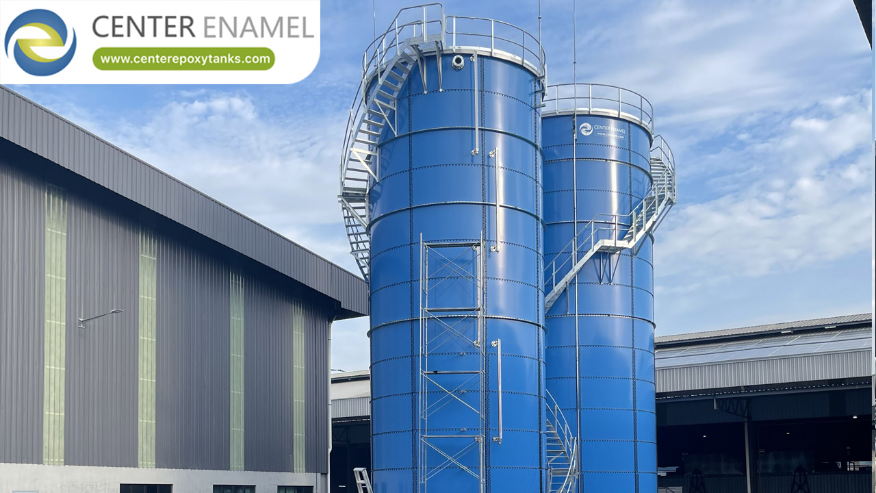
Malaysia Drinking water — GFS (Glass-Fused-to-Steel) bolted tank, φ17.58*21m(H) ×4, total 20380 m3, 2025.
Work With Center Enamel
Center Enamel (Shijiazhuang Zhengzhong Technology Co., Ltd) is a storage-tank and process-equipment manufacturer established in 2008 and headquartered in Shijiazhuang, China. Its product range covers Glass-Fused-to-Steel (GFS) tanks, Fusion Bonded Epoxy (FBE) coated bolted tanks, stainless steel tanks, hot-dip galvanized tanks, welded steel tanks and aluminum geodesic dome roofs. The company holds ISO 9001, ISO 45001, ISO 28765, EN 1090, NSF/ANSI 61, WRAS, FM, CE, LFGB and BSCI certifications and designs to AWWA D103-09 and other recognized international codes. Its manufacturing base produces around 300,000 enamel steel plates per year and has delivered 30,000 installed tank projects, supported by a global distributor network with a 24-hour after-sales response.
Contact Center Enamel — Share your load profile, window and delta-T and we will return a sized volume with usable-volume and loss corrections.