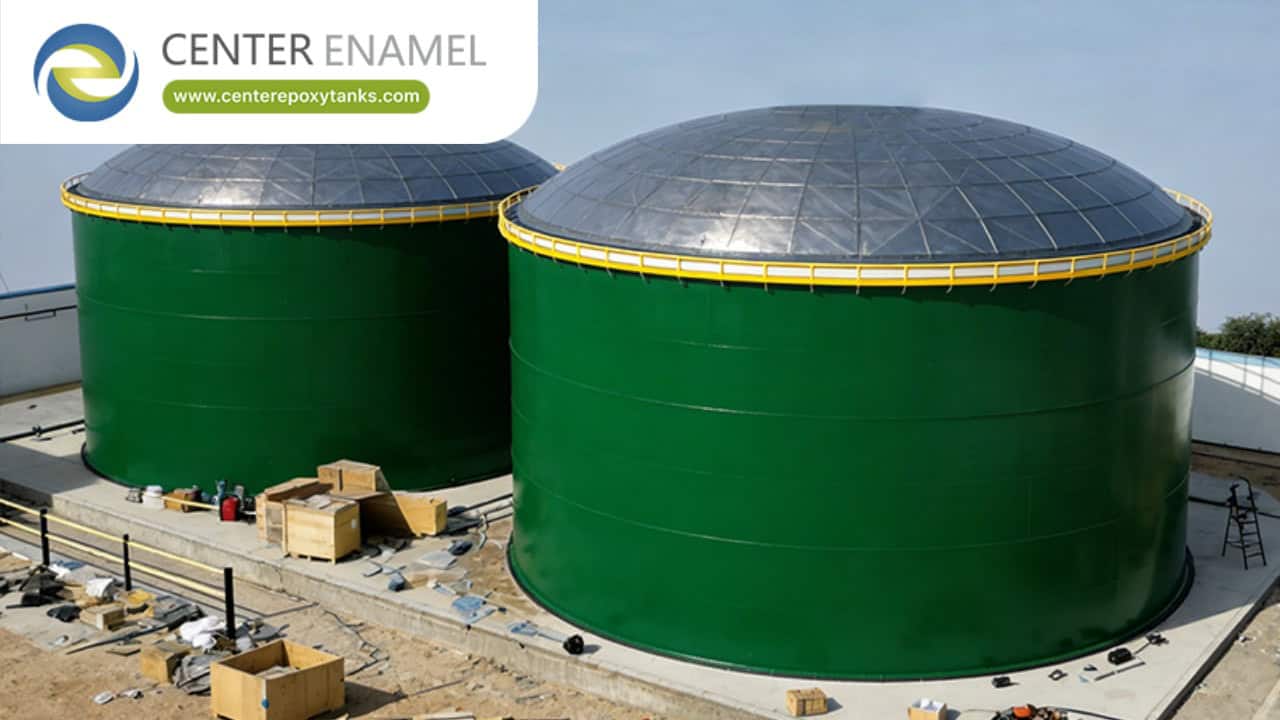
Steel Oil Storage Tank: Welded Construction and the One-Foot Method
The steel oil storage tank looks simple from outside: a vertical cylinder of plate. Inside the specification, though, every course thickness is the result of a calculation that balances hydrostatic head, wind, and seismic load. Welded construction is the route that lets that calculation run to the largest diameters without a joint giving way.
A steel oil storage tank is most often welded to API 650, with shell course thickness set by the one-foot method and then checked for wind ovalization and seismic overturning. Welded carbon steel reaches the largest single-tank volumes, gives a continuous shell with no gaskets to maintain, and carries the NDE and hydrotest discipline that large oil storage demands.
1. Why Welded Construction Dominates
Welding removes the joints that other methods must seal and maintain. At oil-tank scale that continuity is the difference between a shell you trust and a shell you inspect forever. A welded shell reaches 50,000 m3 and beyond with no gasketed courses to maintain across its full 6-40 mm height, which is why it owns the top of the capacity range.
· Continuity: A welded shell has no bolted joints or gaskets across its full height, reducing leak paths.
· Scale: Welded tanks reach 50,000 m3 and beyond, beyond the practical limit of other build methods.
· Code basis: API 650 welded practice is the referenced standard for large oil tanks worldwide.
· Integrity: A continuous shell resists internal pressure and external load as one member.
· Repair path: Welds can be re-examined and repaired with established NDE, unlike sealed joints.
2. The One-Foot Method
The one-foot method sizes each shell course from the liquid head it carries plus a hoop-stress limit. It is why bottom courses are thick and top courses are thin. Each course is calculated one foot at a time up the shell, with a corrosion allowance of 1-3 mm added so the tank still meets the standard after decades of service.
· Head-driven: Each course is calculated for the fluid column above its base, one foot at a time up the shell.
· Thickness taper: Bottom courses are heaviest; the top course is the lightest, following the falling hydrostatic load.
· Stress limit: The formula caps hoop stress so the steel does not yield under the design liquid level.
· Corrosion allowance: Extra thickness is added for future loss, extending service life without a second shell.
· Wind override: Where wind or seismic governs a top course, that case sets the thickness instead of the liquid.
3. Inspection and Stiffening
A welded tank is only as proven as its inspection. Radiography or ultrasonic testing of longitudinal and annular welds, plus a wind girder, turn a stack of plates into a verified structure. RT or UT at 10-100 % of seam length, a hydrotest to 1.25x head, and a dimensional survey are what let a regulator permit the tank and an insurer cover it.
· Weld NDE: Longitudinal and annular welds are examined by RT or UT to the acceptance level written into the purchase order.
· Wind girder: A stiffening ring at the required elevation prevents shell ovalization under wind.
· Hydrotest: The tank is filled and surveyed to confirm no leakage and acceptable settlement before hand-over.
· Annular plate: The bottom ring is thicker to spread shell load into the foundation.
· Dimensional survey: Roundness and plumb are checked so the shell meets the standard geometrically, not just on paper.
Design parameter | Typical value or range | Why it matters |
One-foot rule | Per course | Thick at base |
Capacity | 50,000+ m3 | Welded scale |
Weld NDE | RT / UT | PO acceptance |
Shell plate | 6-40 mm | Hydrostatic head by elevation |
Coating DFT | 0.25-0.40 mm | Verified before shipment |
NDE coverage | 10-100 % | Seam length examined |
Vapor loss | up to 99 % | Standing-loss reduction |
Service life | 30-50 years | Design target |
Operating temp | 20-60 °C | Product and climate |
Limitation to check | Wind/seismic may override | Top course case |
Wind / seismic load | 0.5-1.5 kPa | Roof and shell load |
Foundation settle | 0.1-0.3 m | Controlled subgrade |
Throughput | 50-500 m3/d | Typical draw |
Operating temp | 20-60 °C | Product and climate |
Product density | 800-950 kg/m3 | Typical range |
Design margin | 10-20 % | Allowance in steel |
Aspect | Welded Steel | Alternative Build | Why Welded Wins |
Capacity | 50,000+ m3 | Smaller | Scale |
Joints | Continuous weld | Gasketed | Fewer leaks |
Code | API 650 | Varies | Accepted basis |
NDE | RT / UT | Lesser | Verified |
Life | 30+ years | Varies | With allowance |
Engineering Assurance and Project Support
Every welded oil tank delivered by Shijiazhuang Zhengzhong Technology Co., Ltd. (Center Enamel) is designed to API 650 with shell courses sized by the one-foot method and checked for wind, seismic and hydrostatic load cases, or to EN 14015 and the Eurocodes where the site is European. Shell plate is shot-blasted to Sa 2.5 and coated to a documented dry film thickness, longitudinal and annular plate welds are examined by radiography or ultrasonic testing to the acceptance level written into the purchase order, and every tank is hydrostatically tested and dimensionally surveyed before hand-over. Calculation packs, weld NDE records, and hydrostatic and dimensional surveys are delivered so the welded shell can be re-checked against API 650 at any point in its service life.
A welded steel tank is not stronger because it has more steel; it is stronger because it has fewer joints for the liquid to find, and every one of those joints is examined, not assumed.
Frequently Asked Questions (FAQ)
Why are most steel oil tanks welded?
Welding gives a continuous shell with no bolted joints or gaskets across the full height, reaching 50,000 m3 and beyond where other build methods stop. API 650 welded practice is the globally referenced basis for large oil tanks, and welds can be re-examined and repaired with established NDE.
What is the one-foot method for shell design?
It sizes each shell course from the liquid head above its base, one foot at a time up the shell, capping hoop stress so the steel will not yield at the design level. Bottom courses are thickest and top courses thinnest, following the falling hydrostatic load, with a corrosion allowance added for life.
How are welds and the shell inspected?
Longitudinal and annular welds are examined by radiography or ultrasonics to the purchase-order acceptance level, a wind girder prevents ovalization, and a hydrotest with dimensional survey confirms no leakage and acceptable settlement before hand-over.
What sets welded tanks apart at large capacity?
Only welded construction reaches the largest single-tank volumes with a continuous shell and the NDE and hydrotest discipline that scale demands. The joint-free shell is why welded tanks own the top of the capacity range.