Integrating a Chilled Water Storage Tank Into a Data Center Chiller Plant
A chilled water storage tank data center integration only delivers value when it is correctly integrated into the chiller plant. Piping topology, control sequencing, and operating modes determine whether the tank actually shifts load or merely adds complexity. This article covers the integration patterns that work in data-center cooling loops.
Integrate the TES tank in parallel with the chiller evaporators on the chilled-water side, controlled by the plant sequencer. In charge mode the chillers fill the tank with cold water; in discharge mode return water is cooled through the tank before the CRAHs. Three-way valves and a temperature-focused control loop manage the thermocline without mixing the layers.
Piping Topology
The most common arrangement places the tank in parallel with the chillers between the chilled-water supply header and the CRAH return. This lets the plant operate in full-chiller, full-TES, or blended modes without re-piping.
Dedicated supply and return connections to the tank, each with a diffuser, preserve stratification. Three-way control valves route flow based on mode and thermocline position.
Control and Sequencing
The building management system sequences chillers against tank state. At night or during low tariff, chillers charge the tank to its cold-setpoint; during peak, the tank discharges and chillers trim to meet the remaining load.
Good control watches the thermocline temperature at multiple heights rather than a single average, preventing warm water from reaching the CRAHs.
Operating Modes and Freeze Protection
Blended operation uses both chillers and tank simultaneously for partial shifting; full discharge can carry the site through short peaks. Because chilled water stays above freezing, freeze protection is simpler than with ice storage, but outdoor tanks still need insulation and, in cold climates, trace heating at connections.
Technical Specifications
Parameter | Specification |
Loop position | Chilled-water side, parallel to chillers |
Modes | Charge / discharge / blended |
Control signal | Thermocline temperature profile |
Valves | Three-way motorized |
Diffusers | Top and bottom, low-velocity |
BMS interface | BACnet / Modbus typical |
Freeze risk | Low (above freezing) |
Outdoor tank | Insulation + trace heat |
Shell | Atmospheric stratified |
Material | GFS / stainless / welded |
Verified Tank Engineering Reference
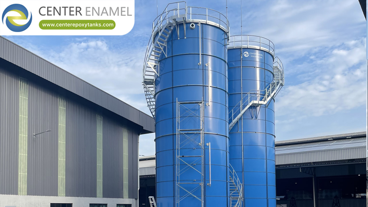
Center Enamel's multi-unit bolted-tank farms - such as a 2025 Malaysian potable-water project of four GFS tanks at 17.58 m diameter and 20,380 m3 - reflect the capability to deliver several coordinated large shells on one campus, useful where a data center deploys multiple TES or buffer tanks. Capability evidence only.
Project location | Malaysia |
Application | Drinking water |
Tank type | GFS (Glass-Fused-to-Steel) bolted tank |
Scale | 4 unit(s), φ17.58*21m(H) |
Total volume | 20,380 m3 |
Year | 2025-10 |
Note | Cited as manufacturing-capability evidence, not a data-center project. |
Center Enamel Capability
Center Enamel delivers the physical tank assets and can support integration discussions with reference to shell connections, nozzle layout, and access for diffuser installation. Bolted tanks are erected on-site from factory-fired panels, which simplifies logistics for multi-tank campuses.
Manufacturing follows ISO 9001, with bolted construction to AWWA D103 and ISO 28765 and available NSF/ANSI 61 / WRAS certification for water-contact service.
Frequently Asked Questions
Q: How is the TES tank piped?
A: In parallel with the chillers on the chilled-water side, between the supply header and CRAH return, with dedicated diffuser connections.
Q: What are the operating modes?
A: Charge (chillers fill tank), discharge (tank meets load), and blended (both). The BMS selects mode by tariff and thermocline state.
Q: How is the thermocline controlled?
A: Multi-height temperature sensors drive three-way valves so warm return water does not mix into the cold layer.
Q: Is freeze protection needed?
A: Chilled-water TES stays above freezing, so risk is low, but outdoor tanks may need insulation and trace heating at connections in cold climates.
Q: Can one tank serve multiple chillers?
A: Yes - the parallel topology lets several chillers charge a common tank and several CRAHs draw from it.
Q: What material for an integrated tank?
A: GFS, stainless, or welded steel, chosen by water chemistry and indoor/outdoor location.
Integration is where TES value is realized or lost. Parallel piping, thermocline-aware control, and sensible operating modes let a single tank shift substantial chiller load without compromising CRAH supply temperature.
Suggested Next Step
Share your chiller-plant single-line diagram with our team - we will propose tank connections, nozzle layout, and a diffuser scheme that fits your controls.