Fire Water Tank Sizing: Design Flow, Duration And Usable Volume
Fire water tank sizing is four inputs: the design flow from the system standard, the duration that flow has to be sustained, the volume the system cannot draw, and the net capacity NFPA 22 recognises between the overflow inlet and the discharge outlet. Multiply the first two, subtract the third, and the fourth is what you must actually buy.
Introduction
Fire water tank sizing fails at review more often than any other tank calculation, and it fails for a consistent reason: the tank is sized to a nameplate volume instead of to a deliverable one. A tank quoted at 1,000 m3 is not a tank that delivers 1,000 m3 to a fire pump. The water below the vortex plate cannot be drawn, the level sits below the fire service level to leave room for the fill valve, and the design flow was calculated at a certain elevation.
This guide sets out the calculation in four steps: the design flow, the required duration, the unusable volume, and the split across tanks if more than one is needed. Each step traces to a named clause or to the system standard that produces the number.
One point should be settled before any arithmetic starts. NFPA 22 does not prescribe tank sizes. Clause 4.1.1 makes size and elevation a function of the fire flow, duration and pressures required by the systems the tank serves, so the tank cannot be sized until the sprinkler or standpipe design is complete.
Why fire tank sizing fails at review
Reviewers reject tank sizes for three recurring reasons. The first is a volume with no datum: a figure is quoted but nobody says whether it is measured to the overflow inlet, the discharge outlet, the vortex plate or the nameplate. The second is a duration with no source, so nobody can tell whether it came from the system standard or from a rule of thumb. The third is an unusable volume that was never deducted.
The pattern underneath all three is that the calculation is presented as a conclusion rather than as a chain. A reviewer who can follow the chain can check it; a reviewer looking at a single number has no choice but to ask for the working.
There is also a sequencing problem that no amount of arithmetic fixes: NFPA 13 is the standard that produces the sprinkler demand, and until that design exists the tank volume is a guess with a number attached to it.
Step 1: the design flow
The design flow is the quantity of water the system needs at its design condition, and it comes from the system design, not from the tank. For a sprinkler system, NFPA 13 sets the design density and the area of application, and the flow follows from those. For a standpipe or hose system, the allowable flow at the hose connection governs. For a combined system, the demands are superposed.
Two details catch people out. A combined system does not take the largest of the demands; it takes the demand that exists when everything is running. And the flow used for sizing must be the flow at the tank, not at the sprinklers: where the tank is a suction source for a fire pump, the pump and pipe friction between them belong in the calculation.
Write the flow into the specification in units that can be checked, and state whether the figure is the demand at the system or at the tank inlet, because the two differ once elevation and friction are added.
Step 2: the required duration
The duration is the second input, and the one most often taken from the wrong source. NFPA 22 does not set durations for fire water tanks; it defers to the standard for the system being supplied. NFPA 13 sets the minimum duration for a sprinkler system based on the hazard classification of the occupancy, and NFPA 20 governs the pump that has to sustain that flow.
The consequence is that a change to the building's use can invalidate the tank. If the occupancy is reclassified, the hazard classification, the sprinkler design flow and the required duration can all change. Clause 4.1.4 makes this explicit from the tank's side: a tank shall be sized so that the stored supply plus reliable automatic refill is sufficient to meet the demand placed on it for the design duration.
That clause also introduces a decision that belongs to the engineer, not to the tank supplier. Where reliable automatic refill is credited, the refill has to be demonstrably dependable and has to restore the required volume within 8 hours, which is the requirement in Clause 4.2.1.4. Where the supply cannot carry that, the full volume has to be stored.
Step 3: unusable volume and the usable reserve
This is the step that separates a sized tank from a quoted tank. NFPA 22 defines net capacity precisely, and it is not the same as the geometric volume. For a suction tank, Clause 4.1.3 sets net capacity as the volume between the inlet of the overflow and the level of the vortex plate. For all other tanks, Clause 4.1.3.1 sets it between the overflow inlet and the discharge outlet.
Two deductions follow. The volume below the vortex plate is not usable, because drawing it cavitates the fire pump, which is why Clause 14.2.13 requires the anti-vortex plate assembly on every suction tank discharge outlet. And the tank is not kept brimming: Clause 14.4.3 requires the level never more than 4 in. (102 mm) below the designated fire service level.
A third deduction appears when a tank does other work. Clause 14.8 covers connections for other than fire protection, and any such draw must enter the tank above the fire protection volume, so process use cannot consume the reserve.
Step 4: splitting the volume across tanks
Splitting the volume across tanks is a normal answer to a large capacity, and where the calculation quietly goes wrong. The arithmetic looks simple: divide the required net capacity by the number of tanks and add the unusable band to each. The trap is that the band does not divide. Each tank has its own dead volume and level tolerance, so two tanks carrying the same net capacity need more gross capacity than one.
The second trap is the suction arrangement. Where two tanks feed one pump, the suction header has to draw the combined flow from both without starving either, and Clause 14.2.12.3.4 constrains the control valve position relative to the pump suction flange. The third is that a break tank sizes differently altogether: Clause 4.1.5 requires at least 15 minutes of pump operation at 150 percent of rated capacity.
The practical rule is that the split has to be justified by the site, not by the purchase order. Construction logistics, a restricted foundation area, a phased commissioning sequence or a future expansion programme are legitimate reasons. Needing to hit one diameter from a manufacturer's panel range is not.
A worked example
The worked example below uses stated assumptions to show the method, not to supply a project answer. Assume a combined sprinkler and hydrant system with a sprinkler design flow of 60 L/s, a hose stream allowance of 40 L/s, and a required duration of 2 hours. The superposed demand is 100 L/s.
1. Step 1, design flow: 60 L/s + 40 L/s = 100 L/s (1,585 gpm).
2. Step 2, duration: 2 hours = 7,200 seconds.
3. Step 3, required net capacity: 100 L/s x 7,200 s = 720 m3.
4. Step 4, unusable volume: the volume below the vortex plate plus the 4 in. (102 mm) level tolerance from 14.4.3, plus any volume credited to other use. Assume 30 m3 for this geometry.
5. Step 5, gross capacity ordered: 720 + 30 = 750 m3.
If the same 720 m3 of net capacity is split across two tanks, each carries 360 m3 of net capacity and its own unusable band. At 15 m3 per tank the pair holds 750 m3 gross for the same 720 m3 of deliverable water.
Every number in that example is an assumption, and a real project replaces each with the figure from the system design and the site geometry.
Common sizing errors and how the AHJ catches them
Each of these has a specific clause behind it, which is what makes them catchable.
· Quoting nominal capacity. The size is stated as a geometric volume. NFPA 22 recognises net capacity, measured between the overflow inlet and the discharge outlet or the vortex plate level (4.1.3 and 4.1.3.1).
· Ignoring the level tolerance. Clause 14.4.3 permits the level to sit up to 4 in. (102 mm) below the fire service level, and that band is not deliverable water.
· Taking the duration from habit rather than the standard. It belongs to the system standard and the occupancy hazard classification, not to the tank specification.
· Sizing before the system design is complete. Clause 4.1.1 ties size and elevation to the fire flow, duration and pressures of the systems served.
· Crediting a refill that cannot be demonstrated. Clause 4.1.4 allows reliable automatic refill to be counted, and 4.2.1.4 requires the supply to restore the required volume within 8 hours.
· Dividing the unusable volume across tanks. Each tank carries its own dead volume and level tolerance, so gross capacity per tank does not divide.
· Forgetting elevation. The design flow is calculated at an elevation, and the tank elevation is part of the answer under 4.1.1.
What the supplier needs from you to quote
A supplier cannot quote a fire water tank without six things, and the request for them is worth making in writing at the enquiry stage so that every bidder is answering the same question.
6. The design flow, with its units and its source: the flow the attached system requires, from the system design.
7. The required duration, with its source: the duration that flow has to be sustained, from the system standard and the occupancy.
8. The elevation and the site constraints: the finished floor level, the foundation type available and the space the tank has to occupy.
9. The governing code and edition: NFPA 22 with the edition, and the construction standard for the tank type.
10. The net capacity basis required: net capacity, the datum it is measured from, and the usable volume already computed by the design engineer.
11. The testing and handover scope: the acceptance test regime and the documentation the owner expects to receive.
Send those six and the quotation is comparable across suppliers, because every bidder is pricing the same vessel against the same duty. Omit any one of them and the quotations differ for reasons that have nothing to do with the tank, and the comparison tells you nothing useful.
The Four Inputs To A Fire Water Tank Size
Input | Where It Comes From | Governing Reference | Common Error |
Design flow | The fire protection system design: sprinkler density and area of application, hose stream allowance, or deluge discharge | NFPA 13 for sprinkler systems; the design flows of the attached systems | Taking the largest single demand instead of the superposed demand on a combined system |
Required duration | The system standard and the occupancy hazard classification | The system standard the tank serves; NFPA 22 4.1.4 defers to it | A duration taken from habit or from another project rather than the occupancy |
Unusable volume | Tank geometry, the vortex plate level and the operating band | NFPA 22 4.1.3 and 4.1.3.1 for net capacity, 14.4.3 for the level tolerance, 14.8 for other-than-fire connections | Ordering the geometric volume and treating all of it as deliverable |
Elevation and site | Survey, foundation type available and the space allocated to the tank | NFPA 22 4.1.1 ties size and elevation to the flow, duration and pressures required | Sizing before the system design is complete, or ignoring the elevation in the flow calculation |
Refill credit | The water supply: is it dependable, and can it restore the volume within 8 hours? | NFPA 22 4.1.4 for the credit, 4.2.1.4 for the 8-hour refill requirement | Crediting a refill that cannot be demonstrated at the required rate |
Break tank volume | The fire pump rating and the required duration | NFPA 22 4.1.5: at least 15 minutes at 150 percent of rated pump capacity | Sizing a break tank like a storage tank rather than as a pump suction buffer |
Worked Example: From Design Flow To Two Tanks
Step | Quantity | Formula | Value In This Example |
1 | Superposed design flow | Q = Q sprinkler + Q hose allowance | 60 L/s + 40 L/s = 100 L/s (1,585 gpm) |
2 | Required duration | t from the system standard | 2 hours = 7,200 s |
3 | Required net capacity | V net = Q x t | 100 L/s x 7,200 s = 720 m3 |
4 | Unusable volume | V dead = volume below vortex plate + level tolerance band | 30 m3 for the assumed geometry |
5 | Gross capacity, single tank | V gross = V net + V dead | 720 + 30 = 750 m3 |
6 | Gross capacity, two equal tanks | V gross = V net + 2 x V dead per tank | 720 + 2 x 15 = 750 m3 for the same deliverable volume |
7 | Refill check | Required volume restored within 8 hours | Assumed satisfied by the site supply, to be confirmed under 4.2.1.4 |
Project Reference
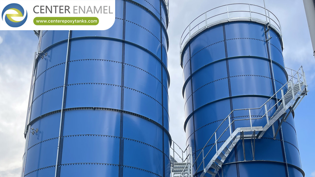
A delivered fire water installation in a glass-fused-to-steel bolted tank, completed in 2024, with a total storage volume of 12,261 m3. The reference is published here to show the scale at which fire water storage is actually built. The project record does not state the design flow, the duration or the net capacity basis for the installation, so none of those is published with it, and it is not offered as a sizing example.
Location | Service | Total Storage Volume | Year |
Not recorded | Fire water service | 12261 m3 total storage volume | 2024 |
About Center Enamel
Center Enamel (Shijiazhuang Zhengzhong Technology Co., Ltd.) designs and fabricates bolted steel storage tanks, welded steel tanks, fusion-bonded epoxy tanks, galvanized tanks, stainless steel vessels, pressure vessels, aluminum geodesic dome roofs and floating roofs. The company has more than 30 years of production experience and has supplied equipment to projects in more than 100 countries. Aluminum geodesic dome roofs are designed and fabricated to API 650 Appendix G, AWWA D108, the Aluminum Design Manual, ASCE 7 and IBC, and the company developed and exported a 72 m diameter aluminum dome roof in 2023. Engineering, fabrication, coating, quality control and site service are handled as one scope, which is why the drawings, the calculation basis and the delivered hardware can be reconciled against each other.
Frequently Asked Questions
How is the required fire water volume calculated?
How is the required fire water volume calculated?Multiply the design flow by the required duration, then deduct the volume the system cannot deliver. The design flow comes from the system design: NFPA 13 for a sprinkler system, and the hose allowance added for a combined system because both operate together. The duration comes from the same system standard and the occupancy hazard classification. The deduction is the volume below the vortex plate on a suction tank and the level tolerance in Clause 14.4.3. NFPA 22 does not prescribe sizes; Clause 4.1.1 makes size and elevation a function of the flow, duration and pressures required.
What is the difference between nominal and usable fire water volume?
What is the difference between nominal and usable fire water volume?Nominal capacity is the geometric volume of the tank. Usable, or net, capacity is what NFPA 22 recognises as deliverable: for a suction tank, Clause 4.1.3 sets it as the volume between the inlet of the overflow and the level of the vortex plate, and for all other tanks Clause 4.1.3.1 sets it as the volume between the inlet of the overflow and the discharge outlet. The difference between the two is the dead volume below the outlet and the operating band below the fire service level.
How long must a fire water tank supply water?
How long must a fire water tank supply water?For the duration the system it serves requires, which is set by the system standard and the occupancy hazard classification rather than by NFPA 22. NFPA 13 governs sprinkler system duration, and NFPA 20 governs the pump that has to sustain the flow. One exception is the break tank: Clause 4.1.5 requires it to hold at least 15 minutes of fire pump operation at 150 percent of rated capacity. And the reserve has to be sufficient for the design duration under Clause 4.1.4, whether that comes from stored water or from reliable automatic refill.
Can the required volume be split across two tanks?
Can the required volume be split across two tanks?Yes, but the gross capacity does not divide the way people expect. Each tank carries its own volume below its own vortex plate and its own level tolerance under Clause 14.4.3, so two tanks providing the same net capacity need more gross capacity than one tank providing the same net capacity. The suction header also has to draw the combined flow without starving either tank, and Clause 14.2.12.3.4 constrains where the control valve sits relative to the fire pump suction flange.
What is the drawdown allowance on a fire water tank?
What is the drawdown allowance on a fire water tank?The volume the system cannot draw, and it has three parts. The first is the water below the vortex plate on a suction tank, which NFPA 22 excludes from net capacity under Clause 4.1.3 because drawing it creates a vortex that cavitates the fire pump. The second is the operating band: Clause 14.4.3 requires the level never to be more than 4 in. (102 mm) below the designated fire service level. The third is any volume credited to a non-fire use, which Clause 14.8 requires to be drawn from above the fire protection volume.
How do sprinkler and hydrant demands combine?
How do sprinkler and hydrant demands combine?By superposition, because both can operate at the same time, so the sizing flow is the sum of the demands rather than the largest of them. The sprinkler demand comes from NFPA 13, the density and area of application for the occupancy hazard classification, and the hydrant or hose stream allowance is added to it. Taking only the larger of the two is the classic way to produce a tank that is short by the smaller demand for the whole of the design duration.
Does the fire pump affect the tank volume?
Does the fire pump affect the tank volume?In three ways. The pump rating sets the maximum flow that can be drawn, so a design flow above the pump rating is not achievable and the tank sizing is wrong. The elevation of the tank relative to the pump sets the static head available, and Clause 4.1.1 ties tank elevation to the pressures required. And the pump's suction requirements set the volume that cannot be drawn, because water below the vortex plate cannot be drawn without cavitating the pump. The 2023 edition of NFPA 22 also requires tank sizing to account for the pump's suction pressure, with the net positive suction head requirement taken from NFPA 20.
The sizing calculation is not difficult, and that is exactly why it goes wrong. Four inputs, one multiplication and one subtraction, and a set of deductions that are easy to leave out because leaving them out produces a perfectly plausible-looking number.
What makes the difference at review is traceability. A capacity that arrives with its datum, its flow, its duration and its elevation attached can be checked in minutes. A capacity that arrives as a number starts a negotiation. Write the chain into the specification, and the tank that arrives is the tank the fire protection design asked for.
Send us the design flow with its source, the required duration, the site elevation and the governing code edition, and we will return the gross capacity with the net capacity basis and the unusable volume shown as separate lines.
Talk To Our Engineering Team
Send the duty, the volume basis, the governing code and the site constraints, and our engineering team will come back with a specification that a supplier can price and a reviewer can approve. We will also tell you plainly when a different tank type or a different scope is the better answer.