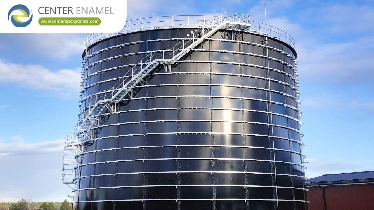
Expansion Tank For Data Centre HVAC: ASME Pressure Vessels For Closed-Loop Systems
Size the expansion tank from the acceptance volume: the system water volume times the water expansion between cold fill and maximum temperature, then divide by the pressure ratio set by the precharge and the relief pressure. Set the precharge to the static pressure at the tank location so the diaphragm only moves when the loop actually expands.
Introduction
A closed chilled water loop is a fixed volume of water trapped between a pump, a chiller and a building full of coils, and when that water warms it expands and has nowhere to go. The expansion tank is the one device that absorbs that expansion without letting system pressure run away to the relief valve or, worse, into negative pressure that pulls air into the loop. It is a small component with a large job, and getting it wrong shows up as nuisance relief discharge or chronic air problems.
This article covers the sizing and the commissioning of the expansion tank as a pressure vessel on a closed loop. We derive the acceptance volume from the system water volume and the temperature swing, show how the expansion factor is read from water properties, compare diaphragm and bladder tanks with air-mounted systems, set the precharge, and explain what a wrong precharge does to the system. Where the tank is built as a vessel it follows ASME BPVC Section VIII, and the loop piping follows ASME B31.9.
The reader here is the HVAC or mechanical engineer who has the system volume and the pressure limits and now needs a defensible tank size and a precharge that will not be reset three times in the first month.
What the expansion tank does in a closed loop
In a closed loop the water cannot expand into the atmosphere, so a rise in temperature raises the specific volume of the water and, at nearly constant mass, raises the pressure unless something gives. The expansion tank provides a compliant volume: an air or gas cushion that is compressed as water enters, so the system pressure rises only to the value the cushion allows rather than to the relief setting.
The tank does three jobs at once. It absorbs the expanded water so the relief valve does not lift on every warm day; it holds a positive pressure at the top of the system so the loop never dips into vacuum and draw in air; and it provides a stable reference that the make-up water system and the pressure sensors read against. Lose any one of those and the plant either spills water or breathes air, and both show up as lost cooling capacity.
Calculating the acceptance volume
The acceptance volume is the volume of water the tank must actually accept as the loop expands from cold fill to its maximum temperature. It is the product of the total system water volume and the fractional expansion of water over that temperature range:
V_acc = V_sys x (rho_cold / rho_hot - 1), where rho is the water density at the cold fill temperature and at the maximum operating temperature. Equivalently, using specific volume v, V_acc = V_sys x (v_hot - v_cold) / v_cold. The system water volume is the sum of the chiller, the coil inventory, the pipe fill and the buffer or storage volume already in the loop; miss it and the tank is sized to the wrong loop.
The total tank volume is larger than the acceptance volume, because the air cushion must compress from the precharge pressure to the maximum pressure across the acceptance volume. The relation is V_tank = V_acc / (1 - (P_pre / P_max)^(1/n)), with P_pre the absolute precharge, P_max the absolute maximum system pressure, and n the polytropic exponent. At the relief pressure the cushion is at its smallest, so the tank must still contain the acceptance volume plus the precharge cushion.
The temperature-dependent expansion factor
The expansion factor is not a constant; it comes from the density or specific volume of water at the two ends of the operating range, and water is awkward about it. Water is densest near 4 degC (39 degF), so a loop that fills cold and warms expands, and the percentage over a chilled-water swing is modest but not negligible.
For a representative chilled loop filling around 7 degC (45 degF) and reaching a warm condition near 60 degC (140 degF), the expansion is on the order of 2 to 5 percent of the system volume, the exact value read from the water property tables at the two temperatures. The point for the engineer is that the factor is set by the temperature extremes actually reached, not by a rule of thumb, so a loop with a high winter setpoint and a low summer peak uses a smaller factor than one with a wide swing, and the tank size follows.
Diaphragm and bladder tanks versus air-mounted systems
Diaphragm and bladder tanks separate the water and the air with a flexible member, so the air charge stays constant and the tank can be installed in any orientation and serviced without draining the whole system. The diaphragm version has the air on one side of a fixed membrane; the bladder version contains the water in a replaceable bag inside the air-filled shell.
Air-mounted or compression-tank systems instead let the water surface meet the air directly, which is simpler but allows the air to dissolve and be carried off by the flow, so the cushion shrinks and the precharge drifts unless the system is recharged. For a data centre where the tank may sit untouched for years, the sealed diaphragm design keeps the cushion stable. Whichever you choose, the shell is a pressure vessel and, where the pressure and volume fall in scope, is built to ASME BPVC Section VIII.
Setting the precharge pressure
The precharge is the air pressure in the tank with no water in it, and the rule is to set it to the static pressure at the tank connection at cold fill, with a small margin. That makes the diaphragm just touch the water at rest, so the tank begins to accept water only when the loop pressure rises above the static value as it warms.
In practice you convert the static head at the tank to pressure, add atmospheric pressure because the precharge is an absolute reading, and set the precharge a few psi below the minimum system operating pressure so the diaphragm is never fully bottomed out. The precharge must stay below the lowest pressure the loop sees in normal operation, or the tank is effectively dead volume and the system loses its compliance. The relief valve setting then defines P_max for the total volume calculation.
The effect of a wrong precharge
A wrong precharge announces itself quickly. If the precharge is too high, the diaphragm is held against the water side and the tank accepts nothing until system pressure climbs past the precharge, so the relief valve lifts on modest expansion and the plant loses water and gains air as it refills.
If the precharge is too low, the tank is full of water at rest and has no cushion to give when the loop cools and contracts, so the pressure can fall toward vacuum and pull air in through the slightest leak or past the make-up valve. Either error produces the same symptoms the tank was meant to prevent, which is why the precharge is checked with a gauge at commissioning and rechecked if the relief lifts or the loop loses pressure for no obvious reason.
Commissioning and the pressure log
Commissioning the expansion tank is a pressure exercise, not a flow one. With the loop filled and at cold static conditions, measure the pressure at the tank connection and compare it to the precharge; they should agree within the tolerance the tank nameplate states. Then raise the loop to operating temperature and log the pressure at the same point.
The commissioning record is a pressure log: static cold pressure, precharge as found and as set, operating pressure at minimum and maximum temperature, and the relief setting. If the operating pressure stays between the precharge and the relief across the temperature swing, the tank is doing its job. File the log with the balanced-flow report, because a year later the precharge that drifted is diagnosed from this baseline, not from memory.
Failure modes and the alarm setpoints
The failure modes are few but repetitive. A waterlogged tank (precharge lost) shows as relief discharge on warm days and low pressure on cold ones; a ruptured diaphragm lets air into the loop and produces chronic air-binding at the coils; an undersized tank lifts the relief on the first warm swing because the acceptance volume exceeded the design.
The alarm setpoints track these. A high-pressure alarm just below the relief setting catches an over-full tank; a low-pressure alarm at the make-up threshold catches a loss of cushion or a leak; and a make-up water meter that turns over when the loop is supposed to be closed is the earliest signal of a tank that is breathing. Set the alarms from the commissioning log, not from generic values, so they fire on a real deviation rather than on normal operation.
Acceptance Volume Calculation Inputs: Quantity, Source, Note
Quantity | Source | Note |
System water volume | Chiller + coils + pipe + storage | Sum the full loop fill |
Cold fill density | Water property table | At the fill temperature |
Hot density | Water property table | At maximum loop temperature |
Precharge (abs) | Static head at tank + atmosphere | Below min operating pressure |
Max pressure (abs) | Relief valve setting + atmosphere | Defines P_max |
Polytropic exponent n | 1.0 isothermal to ~1.3 | Per the charge rate |
Acceptance volume | V_sys x (rho_cold/rho_hot - 1) | Water the tank must hold |
Precharge Setting And The Effect Of Error
Condition | Precharge rule | Symptom if wrong |
Correct | Static at tank + atmosphere, below min | Pressure stays in band |
Too high | Above static, near min pressure | Relief lifts on warm days |
Too low | Below static, near zero | Vacuum draws air on cooling |
Lost cushion | Diaphragm ruptured or leaked | Chronic air-binding at coils |
Undersized | Acceptance volume exceeded | Relief lifts on first swing |
Alarm set | From commissioning log | Fires on real deviation |
About Center Enamel
Center Enamel (Shijiazhuang Zhengzhong Technology Co., Ltd.) designs and fabricates bolted steel storage tanks, welded steel tanks, fusion-bonded epoxy tanks, galvanized tanks, stainless steel vessels, pressure vessels, aluminum geodesic dome roofs and floating roofs. The company has more than 30 years of production experience and has supplied equipment to projects in more than 100 countries. Aluminum geodesic dome roofs are designed and fabricated to API 650 Appendix G, AWWA D108, the Aluminum Design Manual, ASCE 7 and IBC, and the company developed and exported a 72 m diameter aluminum dome roof in 2023. Engineering, fabrication, coating, quality control and site service are handled as one scope, which is why the drawings, the calculation basis and the delivered hardware can be reconciled against each other.
Frequently Asked Questions
How do you size an expansion tank for a chilled water loop?
Size it from the acceptance volume, the system water volume times the fractional expansion of water between cold fill and maximum temperature, then divide by the pressure ratio between the precharge and the relief pressure. V_acc = V_sys x (rho_cold / rho_hot - 1) and V_tank = V_acc / (1 - (P_pre / P_max)^(1/n)). The system water volume must include the chiller, the coils, the pipe fill and any buffer or storage already in the loop, and the temperatures used are the actual extremes the loop reaches.
What is the acceptance volume of an expansion tank?
The acceptance volume is the volume of water the tank must actually hold as the loop expands from cold fill to maximum temperature. It equals the system water volume times the water expansion factor over that range, V_acc = V_sys x (v_hot - v_cold) / v_cold. It is smaller than the total tank volume, because the total also includes the compressed air cushion at the precharge pressure that gives the tank its compliance.
How much does the expansion tank need to accommodate for temperature?
The tank must accommodate the water expansion between cold fill and the maximum operating temperature, read from the water density or specific volume at those two points. For a chilled loop the expansion is typically on the order of 2 to 5 percent of the system volume depending on the temperature swing, and the figure used in the calculation must come from the actual temperatures the loop reaches, not a generic rule.
What precharge pressure should be set?
Set the precharge to the static pressure at the tank connection at cold fill, plus atmospheric pressure because it is an absolute reading, with a few psi margin below the minimum operating pressure. That keeps the diaphragm just touching the water at rest so the tank accepts water only when the loop warms and expands. The precharge must stay below the lowest normal system pressure or the tank becomes dead volume.
What happens if the precharge is wrong?
A too-high precharge holds the diaphragm against the water side so the tank accepts nothing until pressure climbs past it, and the relief valve lifts on modest expansion, losing water and drawing air. A too-low precharge leaves the tank water-filled at rest with no cushion to give on cooling, so pressure can fall toward vacuum and pull air in. Both produce the symptoms the tank was meant to prevent, which is why precharge is checked at commissioning.
Should you use a bladder tank or an air-mounted system?
A sealed diaphragm or bladder tank is usually the better choice for a data centre because the air cushion stays constant and does not dissolve into the flow, so the precharge holds for years without recharge and the tank can be serviced without draining the loop. Air-mounted compression tanks are simpler but lose their cushion as air is carried off, so they need periodic recharging. Where the shell is in scope it is built as an ASME Section VIII vessel.
How is the expansion tank commissioned?
Commission it as a pressure test, not a flow test. With the loop filled and cold, compare the pressure at the tank connection to the precharge and reconcile them, then raise the loop to operating temperature and log the pressure at minimum and maximum conditions against the relief setting. The deliverable is a pressure log: static, precharge as found and set, operating extremes and relief setting, filed with the balance report as the baseline for future diagnosis.
The expansion tank is sized from physics, not habit: the system water volume times the expansion of water over the real temperature swing gives the acceptance volume, and the pressure ratio between precharge and relief gives the total tank volume. Set the precharge to the static pressure at the tank and the tank will only move when the loop actually expands, which is the whole point.
A wrong precharge or an undersized tank reproduces exactly the failures the component was meant to prevent, so commission against a pressure log and set the alarms from that baseline. Send us the system water volume, the temperature extremes and the pressure limits, and we will return a tank size, a precharge value and a commissioning checklist built on the acceptance-volume calculation rather than a catalogue line.
Talk To Our Engineering Team
Send the duty, the volume basis, the governing code and the site constraints, and our engineering team will come back with a specification that a supplier can price and a reviewer can approve. We will also tell you plainly when a different tank type or a different scope is the better answer.