Data Center Thermal Energy Storage Tank Design: Thermocline, Material, and BMS Integration
Designing a data center thermal energy storage tank design is where thermal, structural, and controls engineering meet. This article covers the design decisions for data-center cooling duty, from thermocline to foundation.
Design a data center thermal energy storage tank design around a stable thermocline: size the shell, specify low-momentum diffusers, insulate for the duty, and integrate controls that decide charge/discharge. Material follows water chemistry (GFS, FBE, stainless, welded); code follows AWWA D103 / ISO 28765 or ASME VIII. Good design preserves usable volume and keeps supply temperature in band.
Thermal and Diffuser Design
The diffuser is the heart of the design: ports sized for low velocity so incoming water slides into its density layer without mixing. Manifolds and weirs are common solutions.
The thermocline target (often 0.5-1 m) sets how much of the tank is truly usable, so diffuser performance is a first-class design input, not an afterthought.
Structural and Material Design
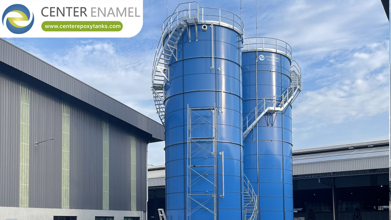
The shell must carry water weight, wind, seismic, and thermal movement. Bolted GFS or FBE panels use certified steel and glass/enamel or epoxy liners; stainless serves pure loops.
For data-center cooling sites, foundation and anchorage are designed from geotech and the chosen aspect ratio, with insulation specified for the chilled duty.
Controls Integration
The tank is only useful if the energy-management system knows when to charge and discharge. Design the control sequence alongside the mechanical design.
Multi-depth sensors feed the controller; alarms protect against thermocline loss and supply temperature excursions.
Technical Specifications
Parameter | Specification |
Tank type | Atmospheric, stratified, or ASME-coded (duty dependent) |
Shell material | bolted glass-fused-to-steel (GFS) |
Capacity range | 20-60,000 m3 (bolted GFS, water/liquid duty) |
Stored medium | Chilled water (sensible) or phase-change medium (latent) |
Design temperature | -10 to 50 C (site / water dependent) |
Corrosion protection | Glass enamel, FBE, stainless, or galvanizing |
Insulation | Optional PU / mineral wool for chilled duty |
Codes / standards | AWWA D103, ISO 28765, EN 1090, ASME VIII |
Erection | Bolted modular panels, short site schedule |
QA | ISO 9001, NSF/ANSI 61, WRAS where applicable |
Foundation | Ring wall or slab per geotech report |
Verified Tank Engineering Reference
Center Enamel's verified record includes a 2022 Drinking water project in Namibia - 4 unit(s), φ41.26*8.4m (H) 4 set, 44,900 m3 total, GFS (Glass-Fused-to-Steel) bolted tank. Center Enamel has no published thermal-energy-storage or data-center TES project; this reference demonstrates the comparable large-tank manufacturing capability relevant to supplying stratified chilled-water TES vessels.
Project location | Namibia |
Application | Drinking water |
Tank type | GFS (Glass-Fused-to-Steel) bolted tank |
Scale | 4 unit(s), φ41.26*8.4m (H) 4 set |
Total volume | 44,900 m3 |
Year | 2022-09 |
Note | Cited as manufacturing-capability evidence, not a thermal-energy-storage project. |
Center Enamel Capability
Center Enamel (Shijiazhuang Zhengzhong Technology) manufactures bolted glass-fused-to-steel (GFS) tanks and ASME-coded pressure vessels for water and thermal-energy storage duty. For thermal-energy-storage (TES) service, the relevant products are large-diameter bolted GFS tanks, FBE-coated tanks, stainless steel tanks, welded shells, and ASME Section VIII vessels for pressurized or stratified chilled-water storage.
Quality is managed under ISO 9001, with bolted tanks built to AWWA D103 and ISO 28765 and available certified to NSF/ANSI 61 and WRAS where potable or indirect-potable contact applies. GFS shells are fired at 820-930 C to fuse the glass enamel, giving a durable, inert liner suited to treated chilled water; stainless and FBE options serve aggressive or high-purity loops. CE's verified delivery record - including a large Namibia installation - demonstrates the manufacturing capability behind these specifications.
Frequently Asked Questions
Q: Which material?
A: GFS, FBE, stainless, or welded steel by water chemistry and code.
Q: What code applies?
A: AWWA D103 / ISO 28765 for bolted; ASME VIII if pressurized.
Q: How are controls designed?
A: With the EMS deciding charge/discharge from tariff, load, and sensors.
Q: What undermines design?
A: Poor diffuser momentum and ignoring thermocline thickness.
Q: How do I design a data center thermal energy storage tank design?
A: Around a stable thermocline: diffuser, shell/material, insulation, and controls designed together.
Q: What is the key component?
A: The diffuser - it preserves stratification and usable volume.
Designing a data center thermal energy storage tank design is integrative: the diffuser, shell, insulation, and controls must agree or usable volume leaks away. Treat the thermocline as the design centre for data-center cooling projects.
Suggested Next Step
Engage our engineers early so thermal and structural design are solved together, not in sequence.