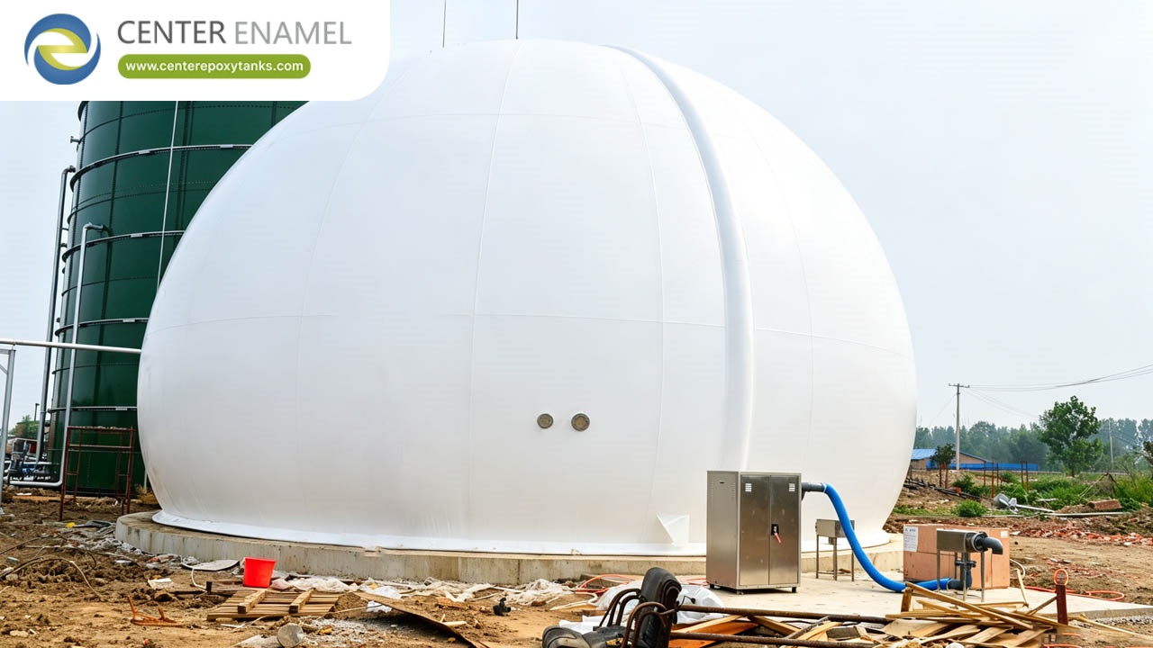
Biogas Holder For Waste Biomass Projects: Containment And Safety
Waste biomass digestion is the variable end of the biogas business. The feedstock changes with the season and the collection stream, the gas composition moves with it, and the holder that stores the gas has to tolerate the variability without becoming the failure point.
This article covers biogas holders for waste biomass projects: the gas characteristics, the containment design for variable production, the contaminant management and the safety systems.
Waste Biomass Gas Characteristics
Waste biomass gas is defined by its variability. The yield moves with the feedstock composition, the methane content moves with the digester condition, and the contaminant load — hydrogen sulphide above all — moves with what arrived in the collection truck.
The holder design has to cover the envelope, not the average: the peak yield, the lowest methane content and the highest contaminant concentration all occur in real operation, and the specification states the envelope it covers.
Variable Production And Containment
Variable production is a containment problem before it is a volume problem. The storage has to absorb the swing between the production peak and the trough without overpressuring or collapsing, and the control band has to be wide enough to ride the swing without venting.
The containment design covers both directions: the volume for the accumulation, the relief for the overpressure and the vacuum protection for the drawdown when production falls and the utilization keeps drawing.
Contaminant Management
The contaminants follow the feedstock. Hydrogen sulphide comes from the sulphur in the organic stream, siloxanes from the treated biogenic waste, and ammonia from the nitrogen-rich feedstocks. Each attacks a different part of the gas train.
The holder’s contaminant exposure is the vapour phase: H2S and moisture together attack the metal components, and the design answers with material selection, condensate drainage and — where the load is high — gas cleanup upstream of the storage.
Contaminant | Source | Holder Impact |
Hydrogen sulphide | Sulphur in the organic feedstock | Corrosion of metal components in the gas path |
Siloxanes | Treated biogenic and sewage-derived waste | Abrasive deposits on downstream equipment |
Ammonia | Nitrogen-rich feedstocks | Corrosion and odour in the gas space |
Moisture | Saturated digester gas | Condensate pooling and localized corrosion |
Overpressure And Underpressure Protection
The pressure protection is the holder’s last mechanical line. The overpressure relief is sized for the credible worst case — blower overrun, downstream blockage, fire exposure — and the underpressure protection covers the drawdown that would collapse the storage volume.
The sizing is a calculation, not a catalogue selection: the relief capacity, the set pressure and the discharge routing are all design outputs recorded in the holder documentation.
Protection Device | Credible Failure Case | Design Output |
Overpressure relief valve | Blower overrun with downstream blockage | Relief capacity and set pressure calculation |
Vacuum relief | Drawdown exceeding production rate | Vacuum set point and capacity record |
Flame arrestor | Flame travelling from utilization equipment | Gas group selection and pipe run record |
Pressure transmitter alarm | Control band excursion | Alarm set points and response matrix |
Flame And Ignition Safety
Biogas is flammable across a wide mixture range, and the gas train carries the flame path from the utilization equipment back toward the digester. The flame arrestors on the gas connections stop that path, and their selection follows the gas group and the pipe run.
The ignition control covers the holder area: the electrical equipment classification, the bonding and earthing of the membrane and structure, and the hot-work discipline that governs every maintenance intervention.
Material Selection For Aggressive Gas
Material selection follows the contaminant load. Where the H2S concentration is high, the metal components in the gas path move to stainless grades or protected steel, and the fasteners and fittings are selected with the same discipline as the structure.
The membrane material follows the gas chemistry too: the specification checks the membrane against the H2S, the moisture and the temperature, with the service life and inspection regime stated against the actual gas analysis rather than a generic envelope.
Inspection And Maintenance Access
The holder has to be inspectable. The access design covers the membrane surface, the anchor and ballast system, the connections and the relief devices — each reachable without dismantling the installation, each on a documented inspection interval.
The maintenance access also covers the gas path: isolation valves that allow a section to be worked without shutting the plant, drain points that can be serviced, and the relief devices that can be tested in place.
Monitoring And Alarm Systems
The monitoring set covers pressure, volume, temperature and gas detection. The alarms are set at the band edges and the detection thresholds, with the response defined for each — the operator action, the automatic action and the escalation path.
The monitoring data also drives the maintenance: the inspection intervals, the relief testing and the membrane condition review all reference the operating record, so the maintenance follows the duty rather than the calendar.
Integration With Gas Utilization
The utilization interface is the pressure and flow contract: the holder and its blower set deliver the gas at the condition the boiler, engine or upgrading unit requires, and the control coordinates the two across the operating range.
The integration covers the contaminant tolerance of the utilization equipment: the engine’s H2S limit or the upgrading unit’s siloxane limit sets the cleanup scope upstream, and the holder sits downstream of that scope with treated gas.
Emergency Procedures
The emergency procedures are written against the failure modes: overpressure, underpressure, gas detection alarm, control failure and fire. Each has a defined operator response, and the design makes the safe state reachable without heroics.
The procedures are part of the delivery: the holder documentation includes the emergency response matrix, the relief device data and the isolation points, so the operations team inherits a working procedure set rather than writing one from scratch.
Center Enamel Waste Biomass Holder Engineering
Center Enamel supplies biogas holders for waste biomass projects with the containment design, contaminant tolerance and safety systems that variable feedstock operation demands. The supply covers the holder, the safety scope and the commissioning support.
Our engineering team supports holder sizing and material selection against the gas analysis and the utilization interface. Contact our engineering team for waste biomass holder procurement guidance on your next project.
About Company
Shijiazhuang Zhengzhong Technology Co.,Ltd(Center Enamel) is a professional manufacturer dedicated to the design and fabrication of bolted storage tanks since 2008. Our products range includes Glass-Fused-to-Steel (GFS) tanks, fusion bonded epoxy tanks, stainless steel tanks, galvanized steel tanks and aluminum geodesic dome roofs. With professional enameling R&D team and nearly 200 enameling patents, Shijiazhuang Zhengzhong Technology Co.,Ltd has become the leader in bolted tanks industry of Asia. Our products are certified to ISO9001, NSF61, EN1090, ISO28765, WRAS ,FM, LFGB, BSCI, IS0 45001 and other international standards.
Shijiazhuang Zhengzhong Technology Co., Ltd is not only the first manufacturer in China which produces Glass-Fused-to-Steel tanks, but also the most experienced professional bolted tanks manufacturer in Asia.The engineering & design, product testing and quality system of Center Enamel Glass-Fused-to-Steel tanks is in strict accordance with AWWA D103-09, OSHA, ISO 28765, NSF/ANSI 61, NFPA and other international standards. Until 2023, Center Enamel bolted tanks have been exported to more than 100 countries including USA, Australia,Canada, Malaysia, Indonesia, Russia, UAE, Panama,Brazil and South Africa etc., the superior tank quality and prompt service gains us worldwide recognition.
As an outstanding containment and cover system provider with decades of industry experience, Shijiazhuang Zhengzhong Technology Co., Ltd sincerely expects to establish long-term cooperation with the local partners throughout the world and make continuous contribution to the development of the industry.
Suggested CTA
Center Enamel delivers biogas holder engineered for waste biomass biogas duty, with waste-to-energy project experience. Contact our engineering team for engineering guidance on your next biogas holder waste biomass project — including sizing, standards compliance and delivery scheduling.
Frequently Asked Questions
Q: What makes waste biomass gas different from other biogas?
A: Its variability. Yield, methane content and contaminant load all move with the feedstock and season, so the holder is specified against an operating envelope rather than an average composition.
Q: Which contaminants matter for holder design?
A: Hydrogen sulphide for corrosion of metal components, siloxanes for downstream deposits, ammonia for corrosion and odour, and moisture for condensate pooling. The material and drainage design answers each.
Q: How is the holder protected against overpressure?
A: With relief devices sized by calculation for the credible worst case — blower overrun, downstream blockage or fire exposure — with the set pressure, capacity and discharge routing recorded in the holder documentation.
Q: What flame safety does a biogas holder need?
A: Flame arrestors on the gas connections sized for the gas group and pipe run, plus ignition control in the holder area through equipment classification, bonding and earthing, and hot-work discipline.
Q: How does the holder handle variable production?
A: The volume absorbs the swing between production peak and trough, the control band is wide enough to ride the swing without venting, and vacuum protection covers the drawdown when production falls while utilization continues.
Q: Why choose Center Enamel for waste biomass holders?
A: Center Enamel supplies biogas holders with containment design, contaminant tolerance and integrated safety systems for variable feedstock operation. Contact our engineering team for procurement guidance.